
Photovoltaic power generating device, and controlling method

a power generation device and photovoltaic technology, applied in the direction of pv power plants, sustainable buildings, pulse techniques, etc., can solve the problems of increasing the length and the number of cables interconnecting these components, and achieve the effects of increasing the distance between the current collecting box and the power conditioner, increasing the length and the number of cables

Active Publication Date: 2012-03-01
SANYO ELECTRIC CO LTD
View PDF1 Cites 169 Cited by
  • Summary
  • Abstract
  • Description
  • Claims
  • Application Information

AI Technical Summary

Benefits of technology

[0010]However, as the photovoltaic power generating device is increased in size, the number of current collecting boxes is also increased. Further, installation sites also become diverse. What is more, the distance between the current collecting box and the power conditioner is also increased, resulting in the increase in the length and the number of cables interconnecting these components.

Problems solved by technology

What is more, the distance between the current collecting box and the power conditioner is also increased, resulting in the increase in the length and the number of cables interconnecting these components.

Method used


Image

  • Photovoltaic power generating device, and controlling method
  • Photovoltaic power generating device, and controlling method
  • Photovoltaic power generating device, and controlling method

Examples


Embodiment Construction

[0023]The embodiments of the invention are described in detail with reference to the accompanying drawings. It is noted that identical or equivalent elements in the drawings will be referred to by like reference numerals and will be explained only once to avoid repetition.

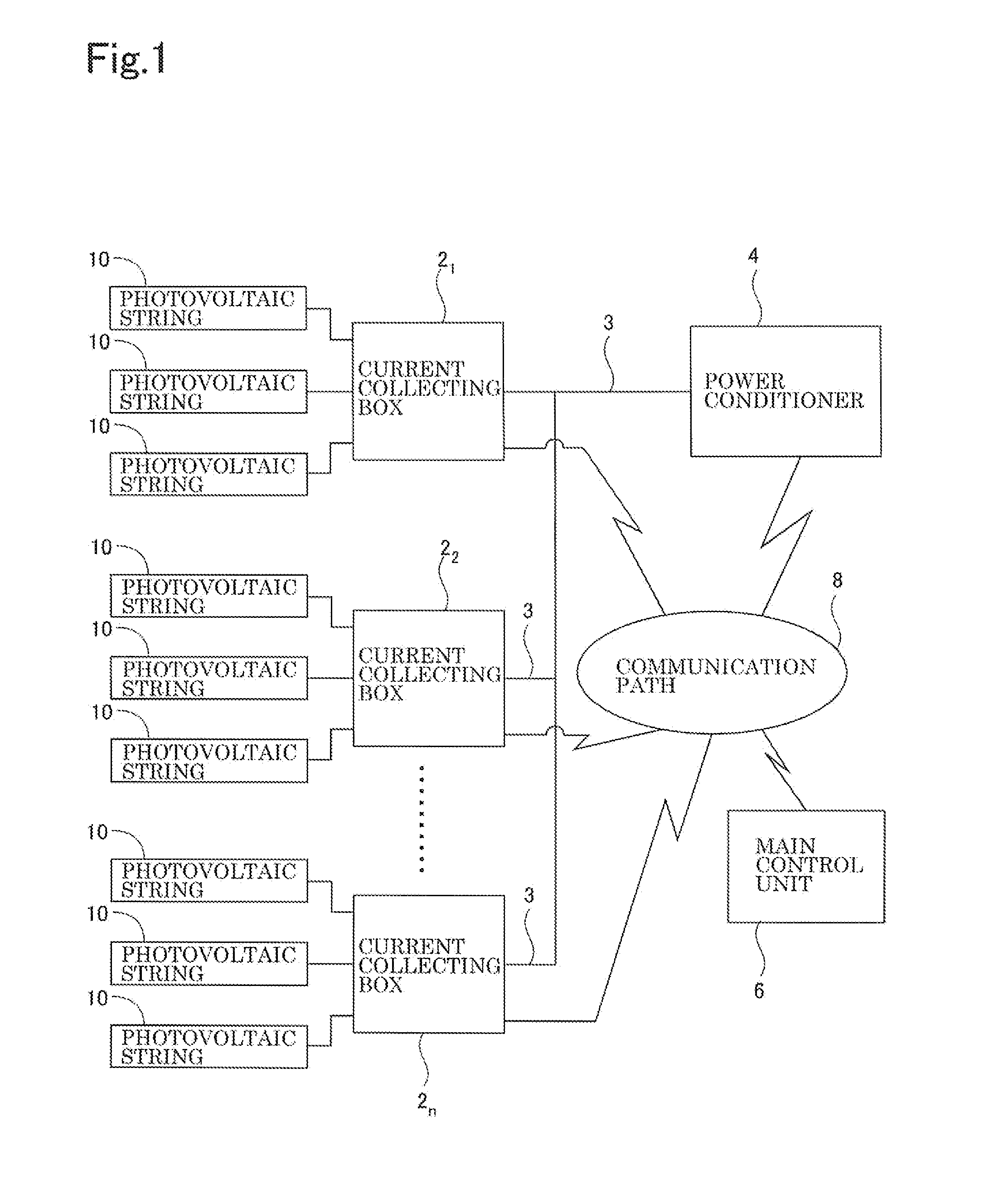
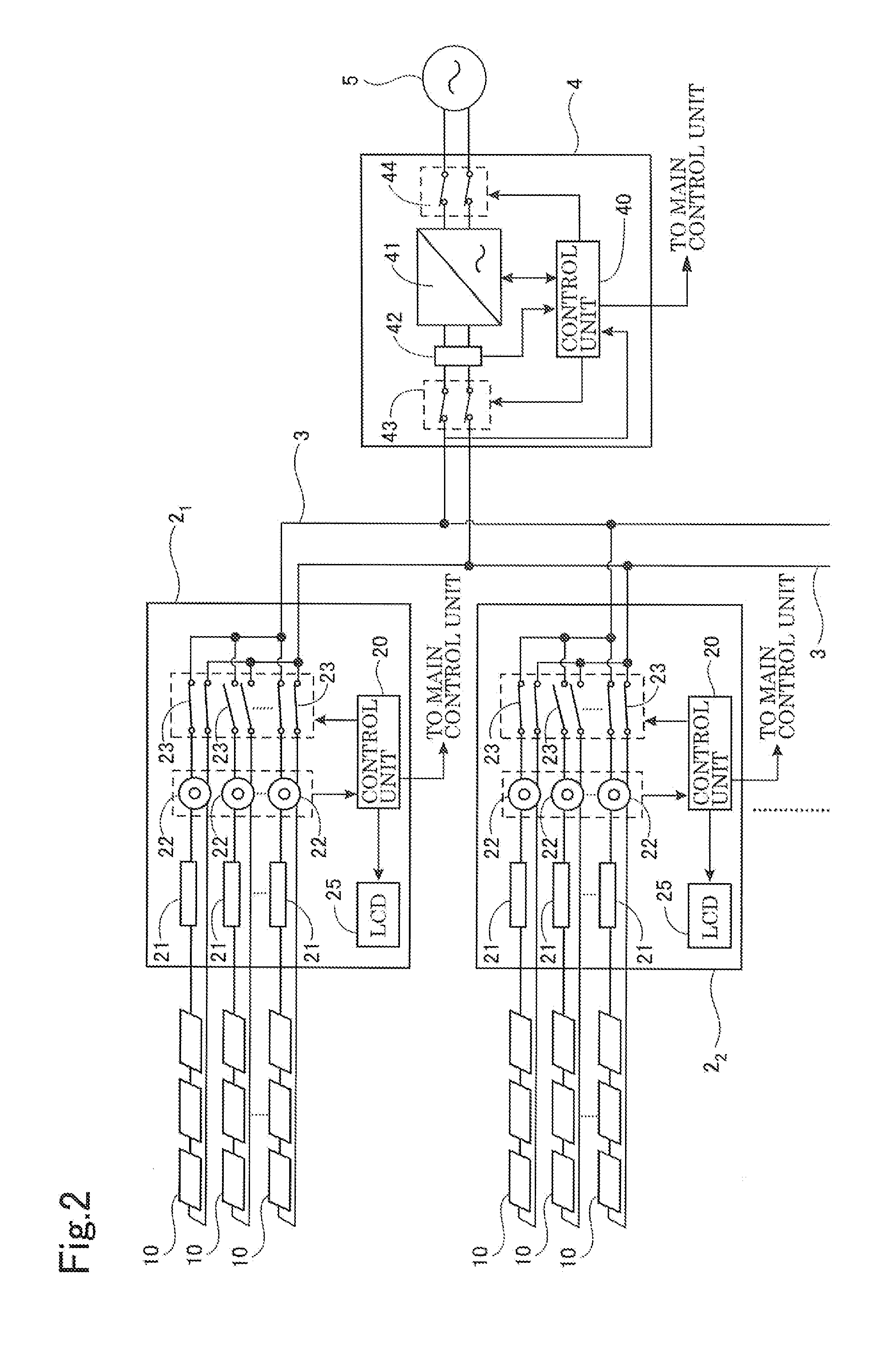
[0024]FIG. 1 is a schematic diagram showing a general arrangement of a photovoltaic power generating device according to the invention. FIG. 2 is a schematic diagram showing a principal arrangement of the photovoltaic power generating device according to the invention. FIG. 3 is a schematic diagram showing the detail of apart including photovoltaic strings and a current collecting box.

[0025]The photovoltaic power generating device according to the embodiment constitutes a medium-scale system, for example, wherein tens of photovoltaic modules having an output on the order of 200 W are interconnected, to a mega solar system wherein at least thousands of such photovoltaic modules are interconnected. The photovoltaic p...


PUM


Abstract

A photovoltaic power generating device comprising a current collecting box side detector for detecting a ground fault in each of the photovoltaic strings, a switch disposed in correspondence to each of the photovoltaic strings and interposed between the photovoltaic string and a connecting cable, a current collecting box including a control unit providing an on / off control of the switch according to the detection result from the detector, a detector for detecting a ground fault in a connecting cable between the current collecting box and the power conditioner, a switch interposed between the connecting cable and the inverter, and a power conditioner having a control unit providing an on / off control of the switch according to the detection result from the detector.

Description

BACKGROUND OF THE INVENTION[0001]1. Field of the Invention[0002]The present invention relates to a photovoltaic power generating device, and controlling method thereof.[0003]2. Description of the Prior Art[0004]A photovoltaic cell generates direct current power by converting the natural energy into electrical energy. With increasing awareness of the recent environmental issues, a photovoltaic power generating device has received attention as a clean power generating device emitting no carbon dioxide which contributes to the global warming.[0005]A large scale photovoltaic power generating system of current interest, such as a mega solar system, aims at achieving an output of more than 1000 kW and includes thousands of photovoltaic modules having an output on the order of 200 W and interconnected to form arrays.[0006]By the way, the above-described photovoltaic power generating system may sometimes encounter ground fault resulting from the deterioration of insulation performance of th...

Claims


Application Information

Patent Timeline
IPC IPC(8): H01L31/042H02J1/12
CPCH02H3/305H02H7/20H01L31/02021Y02B10/14Y02E10/563H02J3/383H02J2300/24H02J3/381Y02B10/10Y02E10/56
Inventor MATSUO, TAKAHISANISHIKAWA, SHUHEISEKINE, TSUYOSHI
Owner SANYO ELECTRIC CO LTD
Learn More