Measuring apparatus
a technology of measuring apparatus and elevation direction, which is applied in the field of measuring apparatus, can solve the problems of deteriorating reconstruction increasing the physical load on the human object, and significantly reducing the image resolution in the elevation direction, so as to improve the image resolution and improve the speed of obtaining image data. , the effect of simple structur
- Summary
- Abstract
- Description
- Claims
- Application Information
AI Technical Summary
Benefits of technology
Problems solved by technology
Method used
Image
Examples
example 1
Transmission of Ultrasonic Wave
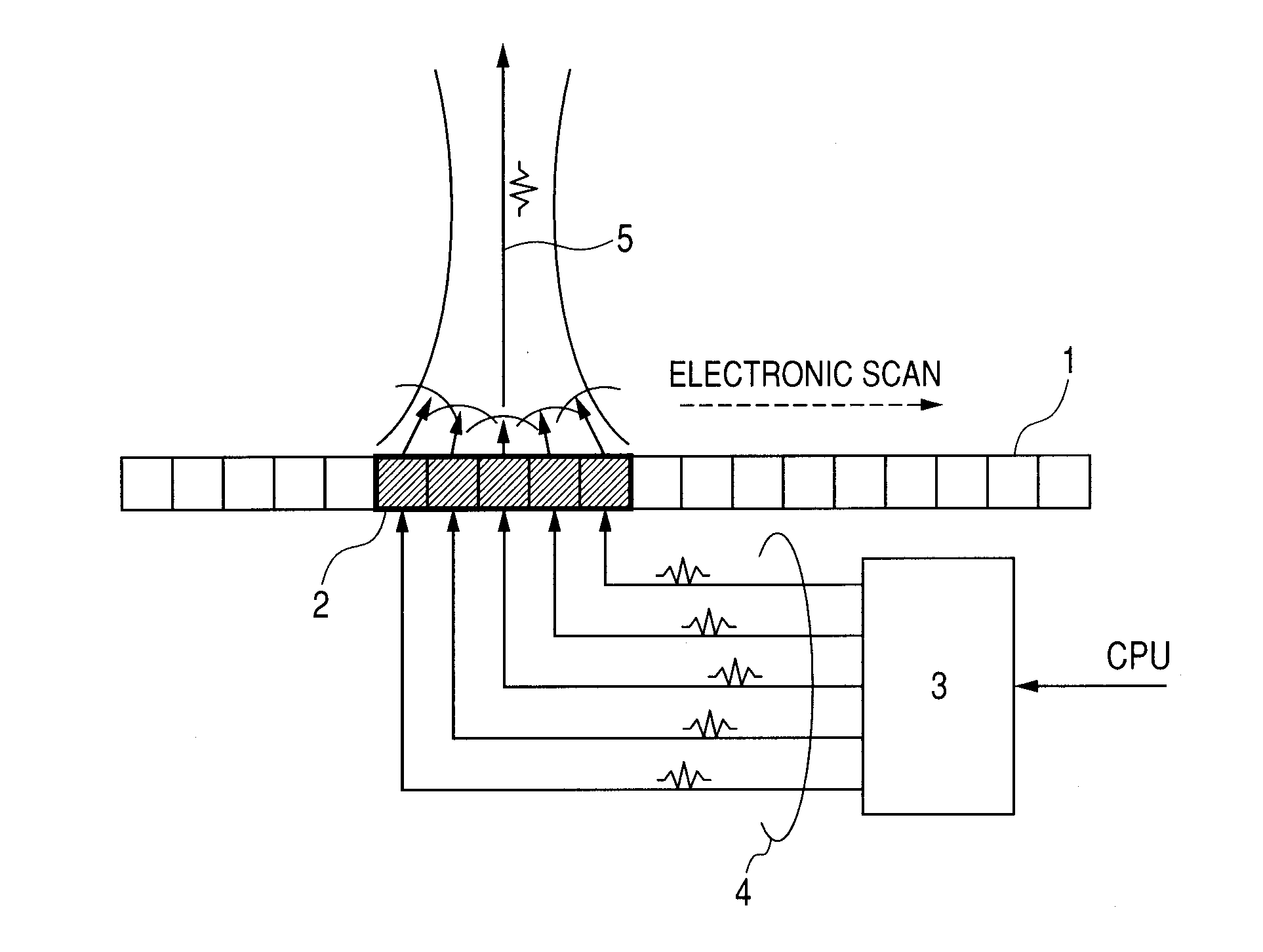
[0029]With reference to FIGS. 1 and 2, Example 1 of the present invention is described. FIG. 1 is a diagram illustrating a principle of a linear scanning method of transmitting an ultrasonic beam 5 using a one-dimensionally arranged probe 1 (hereinafter, simply referred to as “probe”). The ultrasonic wave beam may also be emitted from one transmission and reception element of the probe 1. However, usually, as illustrated in FIG. 1, a plurality of transmission and reception elements are driven (hereinafter, a group of elements to be driven is referred to as “transmission and reception element group 2”), so as to emit a high intensity and high directivity ultrasonic beam 5. In this case, a transmission control circuit 3 applies a pulse-like drive signal 4 to individual transmission and reception elements of the transmission and reception element group 2 at individual timings, so that each transmission and reception element is applied with the drive signa...
example 2
[0050]FIG. 7 illustrates a structure relating to a reception process performed by a measuring apparatus of Example 2. In Example 2, the delay and sum is performed by the apodizing process in which a weight is added to each signal. The apodizing process is effective for performing optimal adjustment of an aperture size according to a focal point position of the delay and sum, or for reducing influence of an interference acoustic wave entering from other directions. In Example 2, weight multiplying circuits 41 and 42 are additionally provided in the preceding stages of the add circuit 8 of the first delay and sum circuit 9 and the add circuit 26 of the second delay and sum circuit 27, respectively, so that the apodizing process may be performed. The weight in this case may be fixed or may be variable according to signal reception time. Note that in Example 2, the apodizing process is performed in both the first delay and sum circuit 9 and the second delay and sum circuit 27, but the a...
example 3
[0051]FIG. 8 illustrates a structure relating to a reception process performed by a measuring apparatus of Example 3. In Example 3, a plurality of second delay and sum circuits are provided, and the plurality of second delay and sum circuits have different focal point positions serving as a reference of the delay and sum (position in the elevation direction).
[0052]In FIG. 6, it is supposed that the focal point P exists in the cross-sectional slice plane obtained by the mechanical scan for a simple description. However, the point P may be at any position in principle. Therefore, in Example 3, the plurality of second delay and sum circuits set the focal point in different cross-sectional slice planes so as to perform the delay and sum process. Specifically, the measuring apparatus of Example 3 includes four second delay and sum circuits constituted of delay adjustment circuits 25a, 25b, 25c, and 25d, and add circuits 26a, 26b, 26c, and 26d. The second delay and sum circuits are each s...
PUM
 Abstract
Description
Claims
Application Information
 - R&D
- Intellectual Property
- Life Sciences
- Materials
- Tech Scout
- Unparalleled Data Quality
- Higher Quality Content
- 60% Fewer Hallucinations
Browse by: Latest US Patents, China's latest patents, Technical Efficacy Thesaurus, Application Domain, Technology Topic, Popular Technical Reports.
© 2025 PatSnap. All rights reserved.Legal|Privacy policy|Modern Slavery Act Transparency Statement|Sitemap|About US| Contact US: help@patsnap.com


