
Touch Panel and Peripheral Circuit Thereof

a peripheral circuit and touch panel technology, applied in the field of touch panel, can solve the problems of high structural defects of the second conductive layer located above the junction area between the first protective layer and the terminal part, and the reliability of signal transmission between the touch panel, so as to improve the connection stability, increase process tolerance, and enhance the effect of connection reliability

Active Publication Date: 2012-02-23
AU OPTRONICS CORP
View PDF2 Cites 15 Cited by
  • Summary
  • Abstract
  • Description
  • Claims
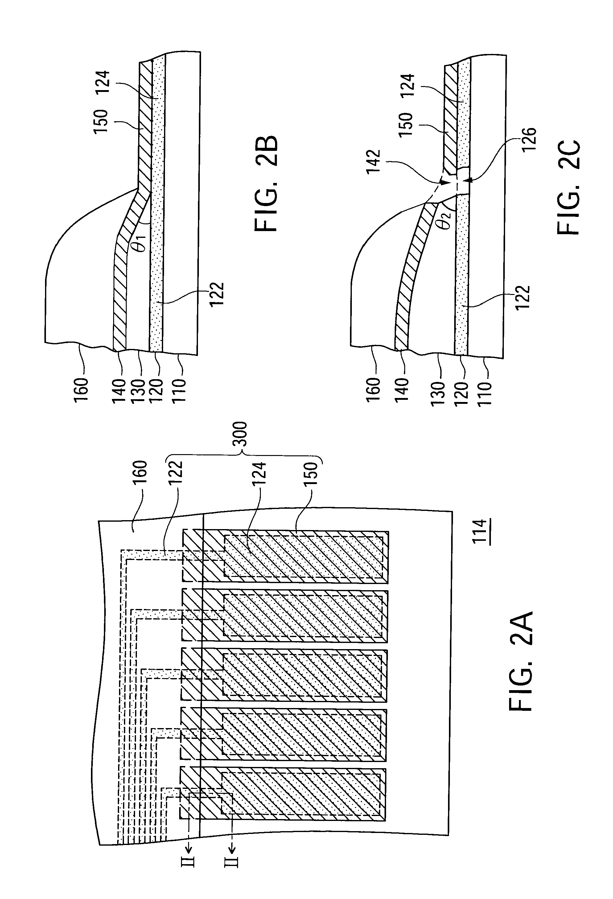
  • Application Information

AI Technical Summary

Benefits of technology

[0008]In view of the above, the present invention provides a touch panel and its peripheral circuit. In the peripheral circuit of the touch panel, a bonding pad structure has better connection stability, thus increasing process tolerance and enhancing the connection reliability between the touch panel and its external peripheral circuit board.
[0010]The second conductive layer located above a junction area between the first protective layer and the terminal part often has structural defects due to various process factors. Thus, when covering the second conductive layer located at this area, the second protective layer can protect possible structural defects of the second conductive layer, thereby overcoming the problems of broken bonding pads.

Problems solved by technology

Therefore, the stability and reliability of signal transmission between the touch panel and the external electrical circuit is an important issue to touch the panel industry.
The second conductive layer located above a junction area between the first protective layer and the terminal part often has structural defects due to various process factors.

Method used


Image

  • Touch Panel and Peripheral Circuit Thereof
  • Touch Panel and Peripheral Circuit Thereof
  • Touch Panel and Peripheral Circuit Thereof

Examples


Embodiment Construction

[0019]Reference will now be made in detail to the present preferred embodiments of the invention, examples of which are illustrated in the accompanying drawings. Wherever possible, the same reference numbers are used in the drawings and the description to refer to the same or like parts.

[0020]According to the above description, the present invention provides a touch panel and its peripheral circuit. In the peripheral circuit of the touch panel, the bonding pad structure has better connection stability, and thus process tolerance can be increased and the connection reliability between the touch panel and its external peripheral circuit board can be enhanced. An exemplified structure of the aforementioned bonding structure and its exemplified fabrication method will be described in the below. For easily understanding the embodiments of the present invention, quite a few technical details will be provided, but not all of the embodiments require all of those technical details. Meanwhile...


PUM


Abstract

A touch panel and a peripheral circuit thereof are provided. Each bonding pad of the peripheral circuit includes a first conductive layer, a first protective layer, a second conductive layer, and a second protective layer sequentially arranged on a substrate from bottom to top. A covered area of the second conductive layer provided by the second protective layer is increased to cover a portion of the second conductive layer located above a junction area between the first protective layer and a terminal part of the first conductive layer, thereby increasing the reliability of the bonding pads.

Description

RELATED APPLICATIONS[0001]This application claims priority to Taiwan Application Serial Number 099127464, filed Aug. 17, 2010, which is herein incorporated by reference.BACKGROUND[0002]1. Field of Invention[0003]The present invention relates to a touch panel. More particularly, the present invention relates to a touch panel and its peripheral circuit.[0004]2. Description of Related Art[0005]Recently, flat-panel displays with small volumes have become the displays popularly used in various electronic products. In order to achieve the objects of operation convenience, concise appearance and integrated functions, many information products have been switched to using a touch panel as an input device from traditional input devices such as a keyboard, a mouse, etc.[0006]With the advanced developments of flat-panel displays and touch-control input devices, in order to allow a user to have a larger viewable image and more convenient operation modes under a limited space, some electronic pro...

Claims


Application Information

Patent Timeline
Patent Type & Authority Applications(United States)
IPC IPC(8): G06F3/041
CPCG06F3/045G06F3/044G06F3/04164
Inventor LAN, KUO-HUACHANG, FU-MINGKUO, CHE-CHENG
Owner AU OPTRONICS CORP
Learn More