
Touch detection techniques for capacitive touch sense systems

a capacitive touch and detection technology, applied in the direction of resistance/reactance/impedence, pulse technique, instruments, etc., can solve the problems of large disruptive capacitance deviations, external noise, interference or other environmental factors, and above two capacitance sensing techniques susceptible to external noise, interference,

Inactive Publication Date: 2012-02-23
MONTEREY RES LLC
View PDF9 Cites 98 Cited by
  • Summary
  • Abstract
  • Description
  • Claims
  • Application Information

AI Technical Summary

Benefits of technology

"This patent is about improving touch detection techniques for capacitance sensors. The patent describes two techniques for measuring capacitance: a relaxation oscillator and a charge transfer mechanism. The patent also discusses the susceptibility of these techniques to external noise and how to account for this. The technical effect of the patent is to provide a reliable capacitance sense interface and control system that can account for these sources of noise and improve touch detection accuracy."

Problems solved by technology

Because the capacitance deviation of a capacitance sense switch due to a finger press is small compared to the underlying capacitance of the switch itself, the above two capacitance sensing techniques can be susceptible to external noise, interference, or other environmental factors.
For example, parasitic capacitances may couple to the user interface, electromagnetic interference (“EMI”) may disrupt capacitance measurements and control signals, deviations in operating temperature can cause thermal expansions and dielectric variations that affect capacitance measurements, user error can result in malfunctions, and so forth.
These environmental factors can often result in disruptive capacitance deviations that are larger than the capacitance changes induced by a finger interaction with the capacitance sense interface.

Method used


Image

  • Touch detection techniques for capacitive touch sense systems
  • Touch detection techniques for capacitive touch sense systems
  • Touch detection techniques for capacitive touch sense systems

Examples


Embodiment Construction

[0027]Embodiments of a system and method for improved capacitive touch sense detection are described herein. In the following description numerous specific details are set forth to provide a thorough understanding of the embodiments. One skilled in the relevant art will recognize, however, that the techniques described herein can be practiced without one or more of the specific details, or with other methods, components, materials, etc. In other instances, well-known structures, materials, or operations are not shown or described in detail to avoid obscuring certain aspects.

[0028]Reference throughout this specification to “one embodiment” or “an embodiment” means that a particular feature, structure, or characteristic described in connection with the embodiment is included in at least one embodiment of the present invention. Thus, the appearances of the phrases “in one embodiment” or “in an embodiment” in various places throughout this specification are not necessarily all referring...


PUM


Abstract

A technique for recognizing and rejecting false activation events related to a capacitance sense interface includes measuring a capacitance value of a capacitance sense element. The measured capacitance value is analyzed to determine a baseline capacitance value for the capacitance sensor. The capacitance sense interface monitors a rate of change of the measured capacitance values and rejects an activation of the capacitance sense element as a non-touch event when the rate of change of the measured capacitance values have a magnitude greater than a threshold level, indicative of a maximum rate of change of a touch event.

Description

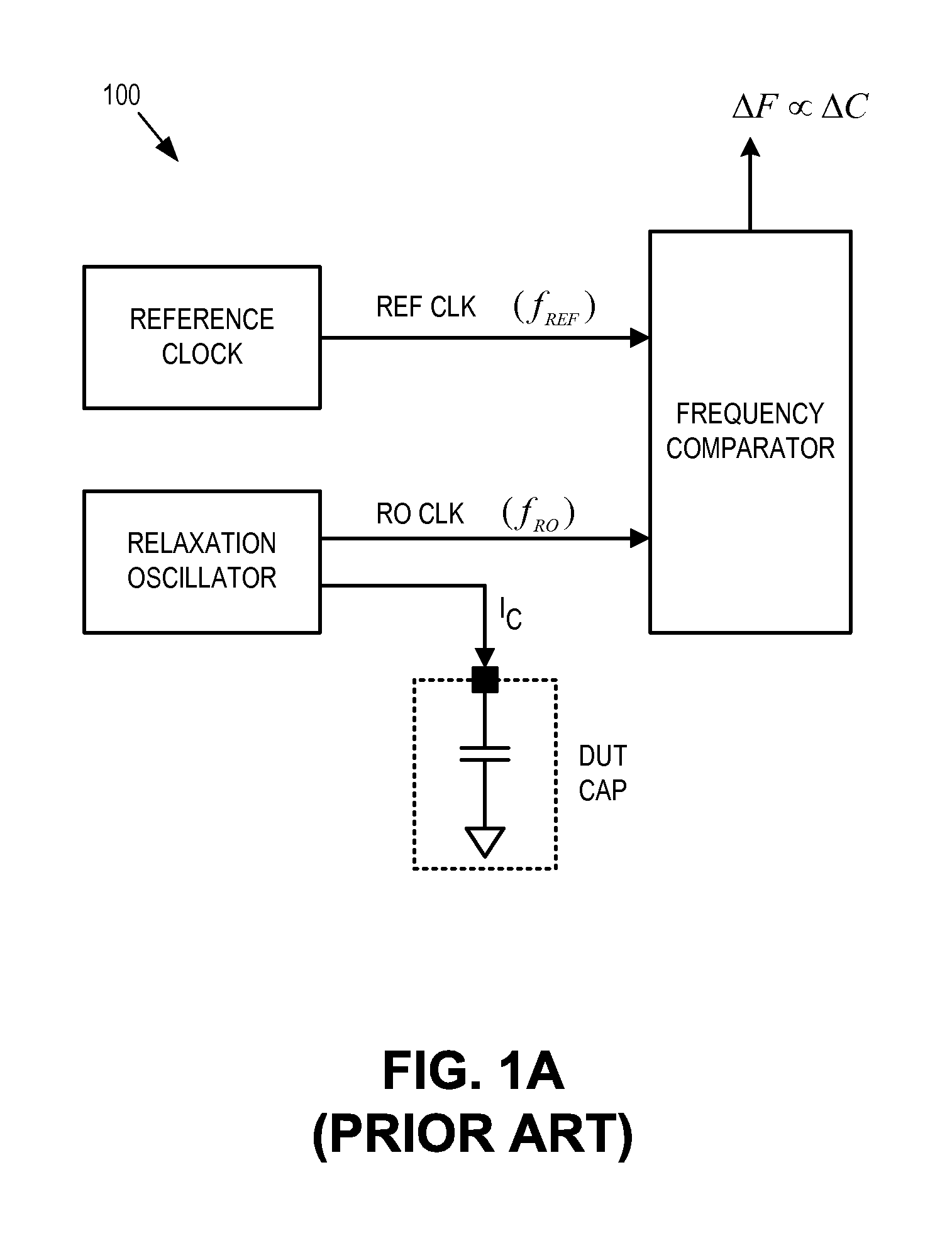
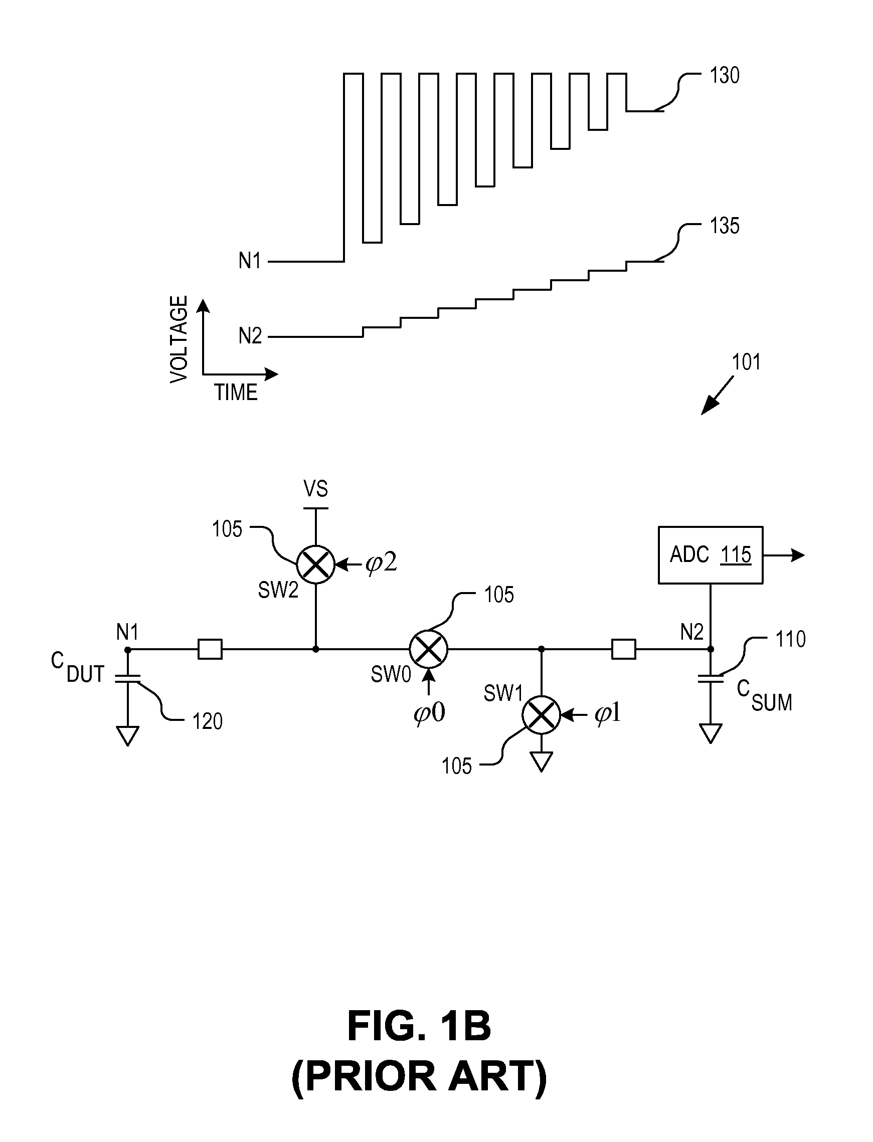
RELATED APPLICATIONS[0001]This application is a continuation of U.S. application Ser. No. 11 / 729,818, filed on Mar. 28, 2007, which claims the benefit of U.S. Provisional Application No. 60 / 788,127, filed on Mar. 31, 2006, each of which are incorporated herein by reference.TECHNICAL FIELD[0002]This disclosure relates generally to capacitance sensing techniques, and in particular but not exclusively, relates to improved touch detection techniques for capacitance sense interfaces.BACKGROUND INFORMATION[0003]Capacitance sensors are used to implement a variety of useful functions including touch sensors (e.g., touch pad, touch dial, touch wheel, etc.), determining the presence of an object, accelerometers, and other functions. FIG. 1A illustrates a conventional capacitance measurement circuit 100 including a relaxation oscillator, a reference clock, and a frequency comparator. The relaxation oscillator is coupled to drive a charging current (IC) in a single direction onto a device under...

Claims


Application Information

Patent Timeline
Patent Type & Authority Applications(United States)
IPC IPC(8): G01R27/26
CPCH03K17/955H03K2217/960705H03K2217/96066H03K17/9622H03K2217/94026G06F3/044G06F3/04182G01R27/2605G06F3/041
Inventor BOKMA, LOUIS W.PAGE, ANDREW C.SEGUINE, DENNIS R.
Owner MONTEREY RES LLC
Learn More