
Touch position detecting device, method of detecting touch position and touch screen display device having the same

a technology of touch position and display device, which is applied in the direction of input/output of user-computer interaction, instruments, computing, etc., can solve the problems of ripple noise, non-uniform sensing data, deteriorating optical properties of lcd device, etc., and achieve the effect of easy detection

Inactive Publication Date: 2006-07-06
SAMSUNG DISPLAY CO LTD
View PDF8 Cites 196 Cited by
  • Summary
  • Abstract
  • Description
  • Claims
  • Application Information

AI Technical Summary

Benefits of technology

[0012] The invention provides a touch position detecting device for simplifying a process of detecting a touch position.
[0013] The invention also provides a touch position detecting method for simplifying the process of detecting a touch position.
[0024] The touch position detecting device may also further include a filter eliminating a noise element by comparing a previously detected touch position with a touch position currently detected.
[0037] Therefore, the touch position is easily detected by determining a difference between the reference data and sensing data at a certain time.

Problems solved by technology

Therefore, an air gap or the adhesive, which has different refractivity from that of the LCD device and / or the touch screen panel, is disposed between the LCD panel and the touch panel device, thereby deteriorating optical properties of the LCD device.
First, the sensing data is non-uniform, and includes ripple noise to some degree.
Additionally, the sensing data may interfere with an image data signal to create noise, thereby lowering a signal-to-noise ratio (“SNR”), and making exact detection of the touch position difficult.
Thus, the panel has a somewhat heavy process load.
Third, much time is consumed when the sensing data is processed by using a segment method and a pre-processing method, which include a smoothing filter (low-pass filter), a sharpening filter (high-pass filter), an additional image transferring process, and a mapping process for transferred images.

Method used


Image

  • Touch position detecting device, method of detecting touch position and touch screen display device having the same
  • Touch position detecting device, method of detecting touch position and touch screen display device having the same
  • Touch position detecting device, method of detecting touch position and touch screen display device having the same

Examples


Embodiment Construction

[0050] Accordingly, while the invention is susceptible to various modifications and alternative forms, specific embodiments thereof are shown by way of example in the drawings and will herein be described in detail. It should be understood, however, that there is no intent to limit the invention to the particular forms disclosed, but on the contrary, the invention is to cover all modifications, equivalents, and alternatives falling within the spirit and scope of the invention as defined by the claims. Like numbers refer to like elements throughout the description of the figures.

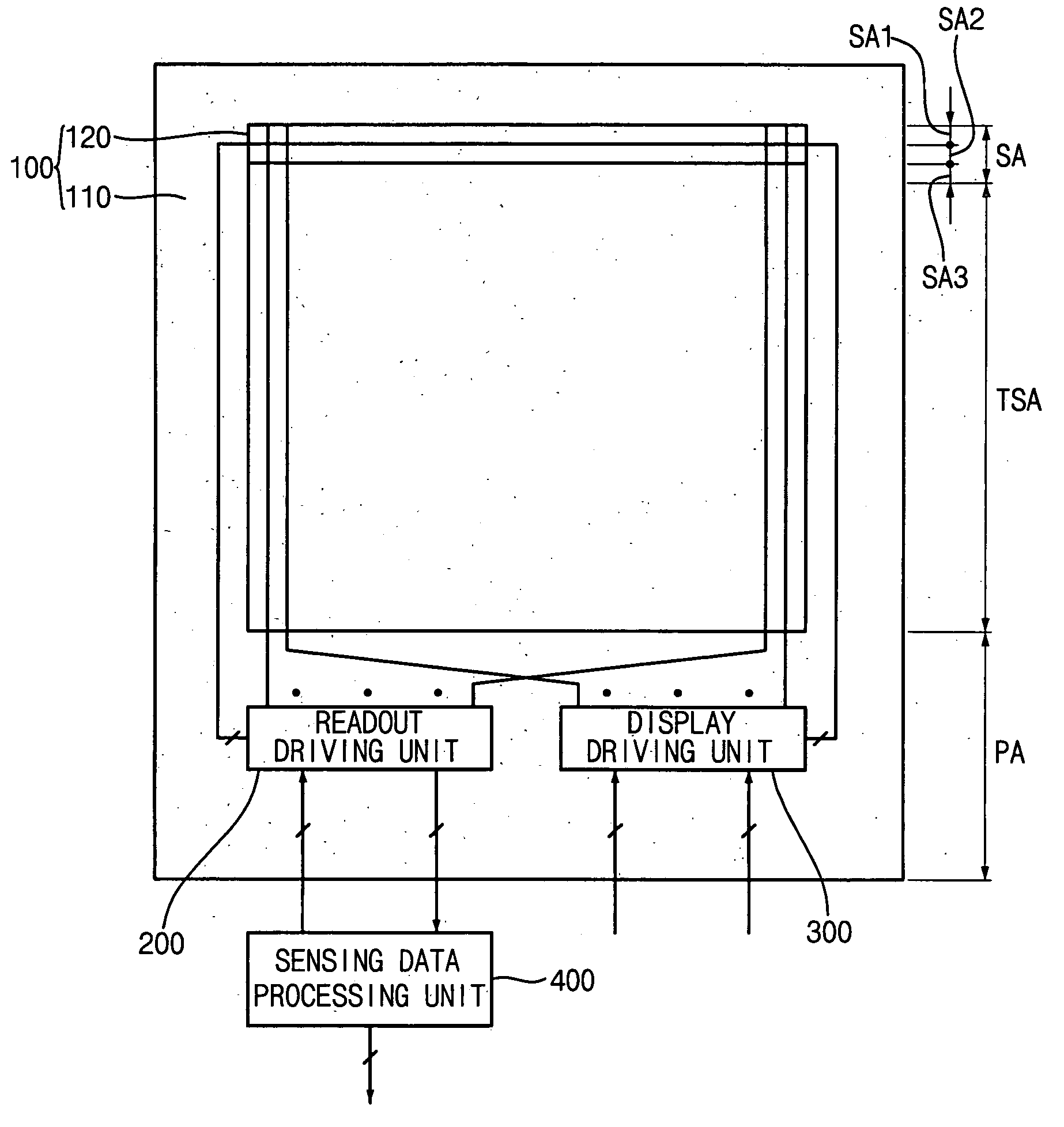
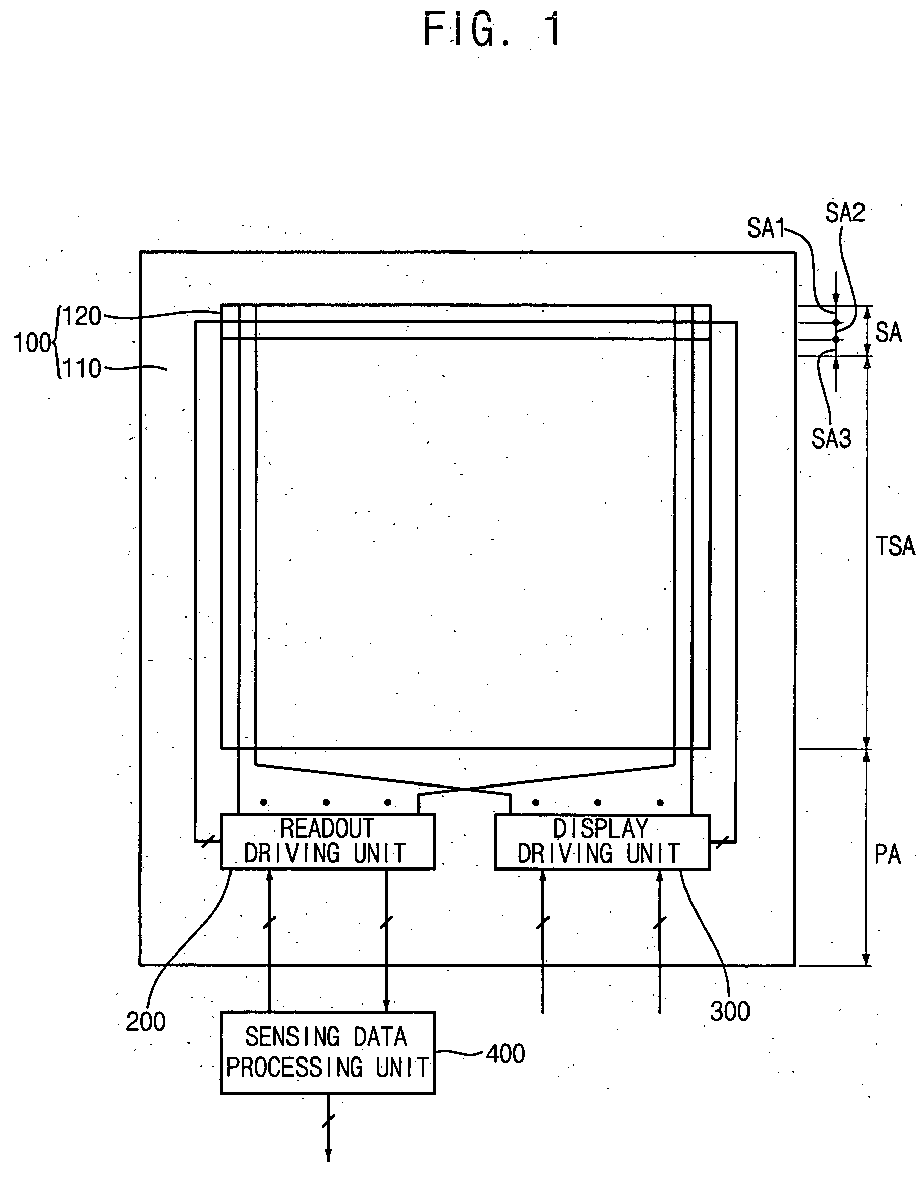
[0051]FIG. 1 is a plan view illustrating an exemplary embodiment of a display device according to the invention.

[0052] Referring to FIG. 1, the display device includes a display panel 100, a readout driving unit 200, a display driving unit 300, and a sensing data processing unit 400.

[0053] The display panel 100 includes an array substrate 110, a color filter substrate 120, and a liquid crystal layer 130 (s...


PUM


Abstract

A touch position detecting method, a device using the method, and a touch screen display device having the device are disclosed. A touch sensing unit senses a touch event and outputs a sensing data. A reference update unit updates a reference data with an n-th frame sensing data provided from the touch sensing unit, based on a predetermined update signal. A position detecting unit detects the touch position by using the reference data and an (n+i)-th frame sensing data from the touch sensing unit. Therefore, the touch position is easily detected by determining a difference between the reference data and the sensing data at a certain time.

Description

[0001] This application claims priority to Korean Patent Application No. 2004-117752, filed on Dec. 31, 2004 and all the benefits accruing therefrom under 35 U.S.C. §119, and the contents of which in its entirety are herein incorporated by reference. BACKGROUND OF THE INVENTION [0002] 1. Field of the Invention [0003] The present invention relates to a touch position detecting device, a method of detecting a touch position, and a touch screen display device having the touch position detecting device. More particularly, the present invention relates to a touch position detecting device facilitating detection of a touch position, a method of detecting a touch position, and a touch screen display device having the touch position detecting device. [0004] 2. Description of the Related Art [0005] Generally, a touch screen panel is an inputting device disposed on a liquid crystal display (“LCD”) panel in order to input data by a finger or a physical object such as a pen. The touch screen pa...

Claims


Application Information

Patent Timeline
IPC IPC(8): G09G5/00
CPCG02F1/13338G02F1/1362G06F3/0412G09G3/3406G06F3/042G06F3/03
Inventor PARK, JONG-WOUNGKIM, HYUNG-GUELLEE, JOO-HYUNGCHO, MAN-SEUNGUH, KEE-HANCHA, YOUNG-OK
Owner SAMSUNG DISPLAY CO LTD
Learn More