
Coil apparatus and non-contact power transmission apparatus

a power transmission apparatus and coil technology, applied in the direction of transformer/inductance circuit, circuit arrangement, inductance, etc., can solve the problem of power transmission efficiency decline, and achieve the effect of improving power transmission efficiency

Active Publication Date: 2012-02-23
TDK CORPARATION
View PDF19 Cites 16 Cited by
  • Summary
  • Abstract
  • Description
  • Claims
  • Application Information

AI Technical Summary

Benefits of technology

[0011]The present invention was devised in view of the foregoing, an object thereof being to provide a coil apparatus and a non-contact power transmission apparatus in which the power transmission efficiency is raised.
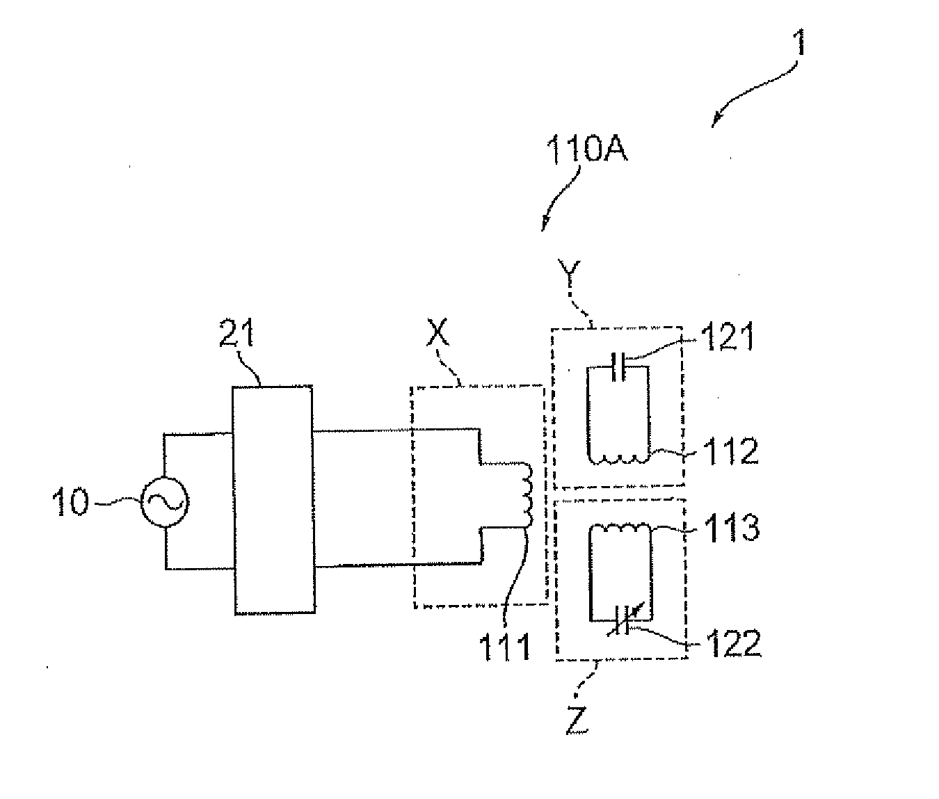
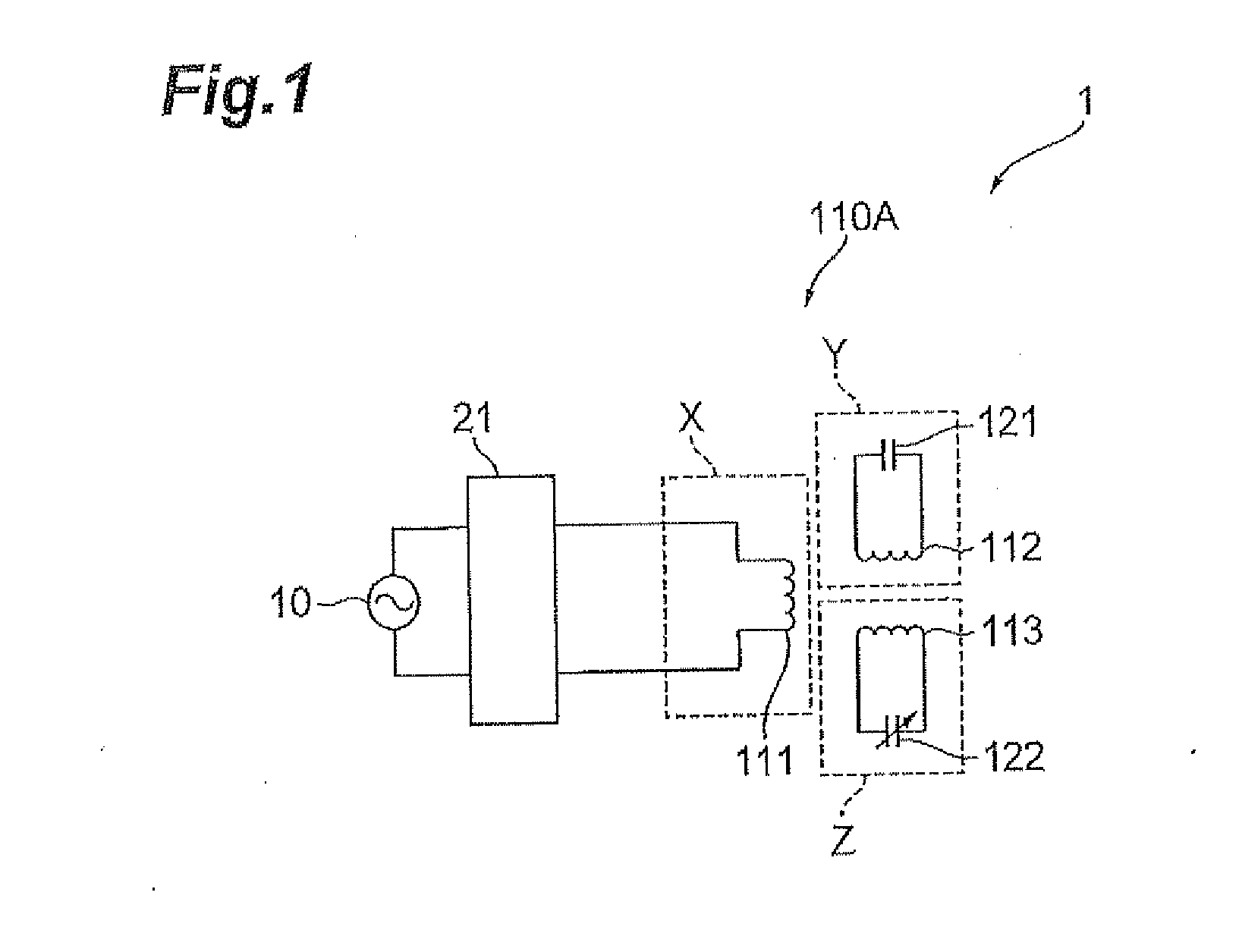
[0013]In the coil apparatus described above, since at least one of the power transmission coil apparatus and the power receive coil apparatus comprises a second resonance circuit which couples magnetically with the first resonance circuit, then it is possible to correct divergence in the resonance frequency occurring in the power transmission coil apparatus and the power receive coil apparatus, by means of the second resonance circuit. Therefore, it is possible to reduce the divergence in the resonance frequency which occurs in the power transmission coil apparatus and the power receive coil apparatus, and the power transmission efficiency is raised. Furthermore, since there is no need to modify the excitation coil or the transmission coil when adjusting for divergence in the resonance frequencies, it is possible to adjust for divergence easily, and the power transmission efficiency can be raised easily.
[0018]According to the present invention, a coil apparatus and a non-contact power transmission apparatus having improved power transmission efficiency are provided.

Problems solved by technology

For this reason, divergence in the resonance frequency occurs in the power transmission side transmission coil components of the power transmission side coil apparatus and the power receiver side transmission coil components of the power receiver side coil apparatus, and there is a problem in that power transmission efficiency may decline.

Method used


Image

  • Coil apparatus and non-contact power transmission apparatus
  • Coil apparatus and non-contact power transmission apparatus
  • Coil apparatus and non-contact power transmission apparatus

Examples


Embodiment Construction

[0034]Below, a mode of implementing the present invention is described in detail with reference to the accompanying drawings. In the description of the drawings, the same elements are labeled with the same reference numerals, and repeated description is omitted.

Prior Art

[0035]Firstly, before describing the coil apparatus relating to the present invention, the general composition of a magnetic resonance type of coil apparatus will be described with reference to FIGS. 13 to 15. FIG. 13 is a diagram showing a composition of a coil apparatus for a non-contact power transmission apparatus, which is constituted by a power transmission side coil apparatus and a power receiver side coil apparatus. In the coil apparatus 100, the left-hand side is a power transmission side coil apparatus 110 and the right-hand side is a power receiver side coil apparatus 210. The power transmission side coil apparatus 110 is constituted by a transmission coil 112 which performs power transmission by using mag...


PUM


Abstract

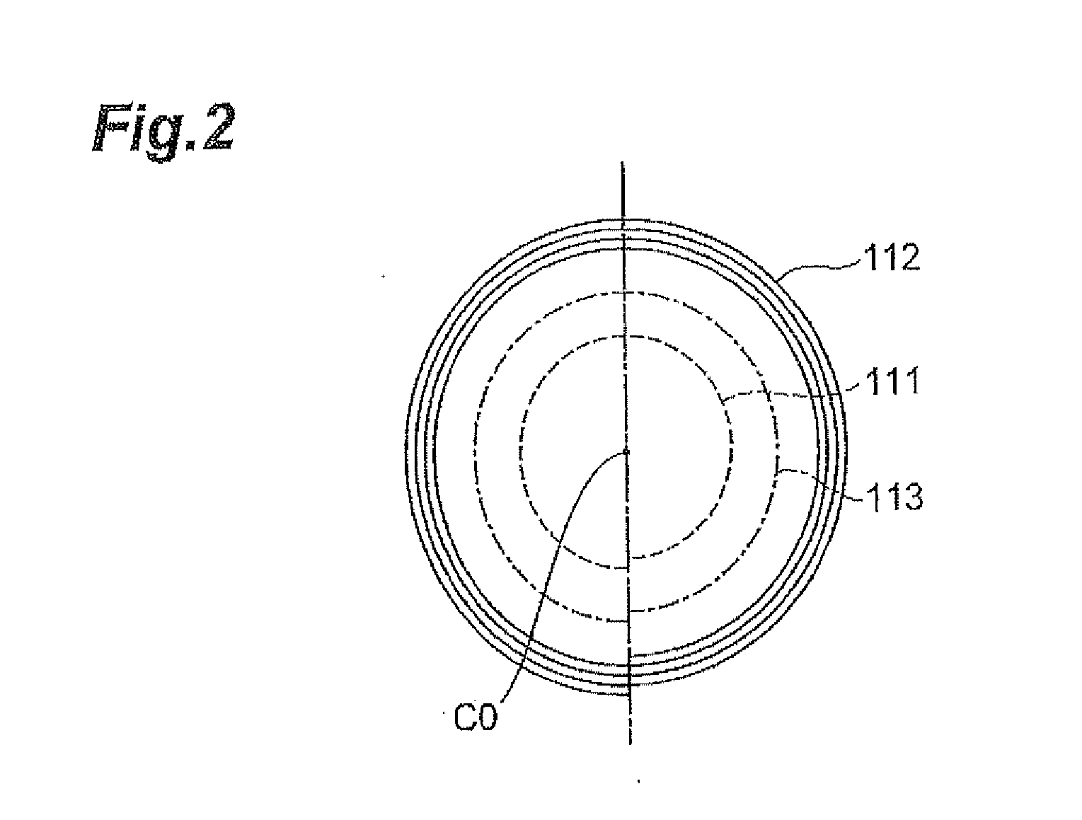
A coil apparatus and a non-contact power transmission apparatus having improved power transmission efficiency are provided. A power transmission side coil apparatus comprises: an excitation coil (second winding section) which transmits AC power supplied from a power source to a transmission coil; a resonance circuit (first resonance circuit) which is formed by a capacitor (first capacitance element) and a transmission coil (first winding section) which is connected to this capacitor and which transmits AC power from the excitation coil to a power receive side coil apparatus; and a resonance circuit (second resonance circuit) which is formed by a variable capacitor (second capacitance element) and a control coil (third winding section) which is connected to this variable capacitor and which resonates with the transmission coil.

Description

BACKGROUND OF THE INVENTION[0001]1. Field of the Invention[0002]The present invention relates to a coil apparatus and a non-contact power transmission apparatus.[0003]2. Related Background Art[0004]Magnetic resonance type power transmission which is capable of supplying power with high efficiency over relatively moderate distances by matching the resonance frequencies of a power transmission (power feed) side and a power receiver side has received attention as a non-contact power transmission technology. This technology is capable of transmitting power at high efficiency when the resonance frequencies of the power transmission side coil and the power receiver side coil are matching.[0005]In power transmission by magnetic resonance, it is known that the power transmission efficiency and the transmission distance are dependent on the Quality Factor (Q) of the coil and the coupling coefficient k of the two coils. The coupling coefficient between the coils becomes lower as the distance ...

Claims


Application Information

Patent Timeline
IPC IPC(8): H02J17/00H01F38/14
CPCH02J5/005H01F38/14H02J50/40H02J50/12H02J50/70
Inventor SAITOH, YOSHIHIRO
Owner TDK CORPARATION
Learn More