
Annular Device for Radial Displacements of Interconnected Parts

a technology of interconnected parts and annular devices, which is applied in the direction of drilling accessories, directional drilling, drilling machines and methods, etc., can solve the problems of short travel, difficult to obtain accurate position control, and not always the best,

Active Publication Date: 2012-02-23
BREAKTHROUGH DESIGN
View PDF0 Cites 28 Cited by
  • Summary
  • Abstract
  • Description
  • Claims
  • Application Information

AI Technical Summary

Benefits of technology

[0013]The present invention is based on the development and preparation of an advantageously bidirectional system for generating esse

Problems solved by technology

These devices meet certain objectives but they do not always make it possible to achieve the best results in all circumstances.
But such jacks generally operate at high pressure and offer short travel in such an environment.
Furthermore, they are difficult to instrument in order to obtain accurate position control.
These offer a high load and expansion capacity with low operating pressures, but they are fragile, especially at high temperature, and lack rigidity.
But the design of these systems makes them generally irreversible and it is essentially proposed that they be associated with needle bearings.
Their drive necessitates complex control systems and it generally necessitates two clutches or two independent motor drives.
Also, wedge systems have been proposed, also capable of generating high stresses, but the implementation of which is extremely delicate in an annular space and which are by nature better suited to a unidirectional mode.
It is universally accepted that the reliability of a system is more often inversely proportionate to its complexity, which is itself also an important cost factor, both for manufacture and for maintenance.

Method used


Image

  • Annular Device for Radial Displacements of Interconnected Parts
  • Annular Device for Radial Displacements of Interconnected Parts
  • Annular Device for Radial Displacements of Interconnected Parts

Examples


Embodiment Construction

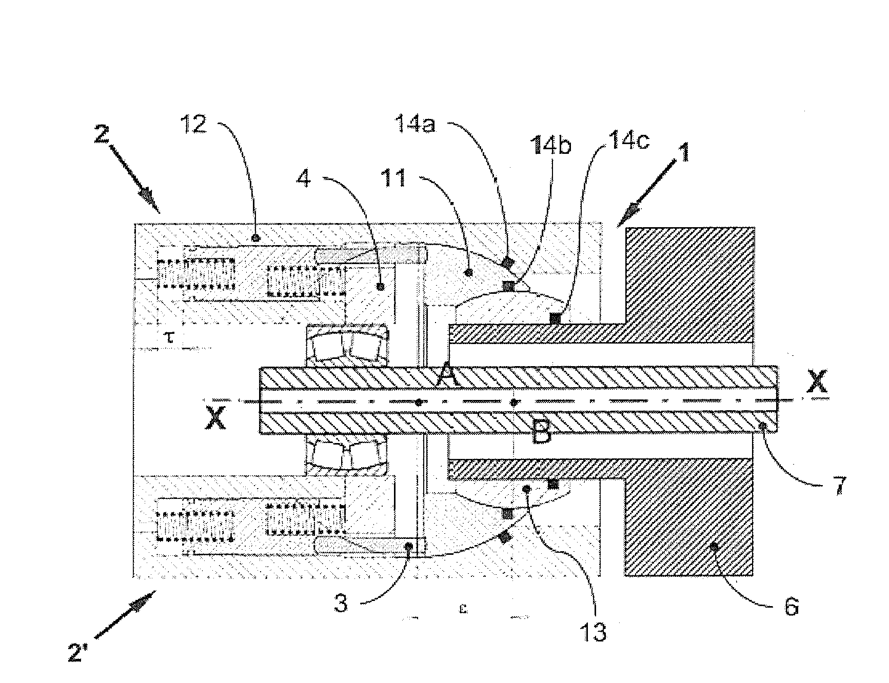
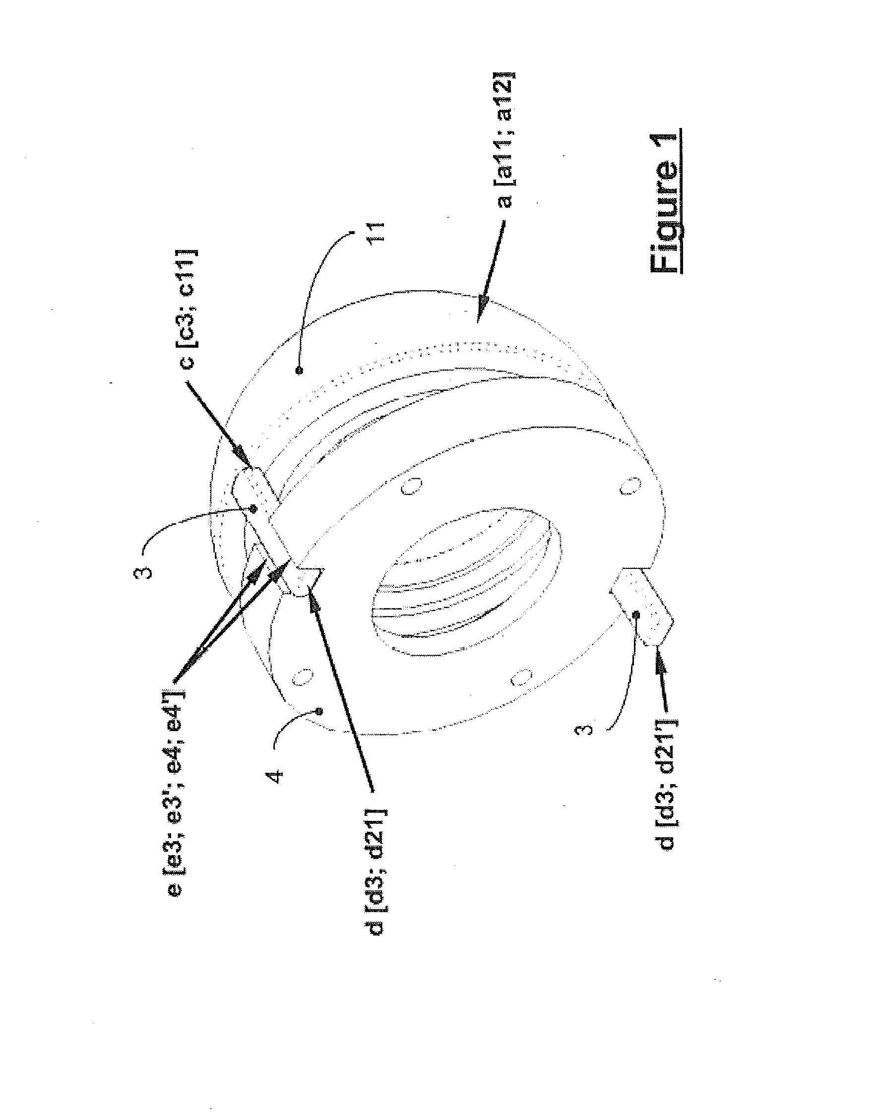
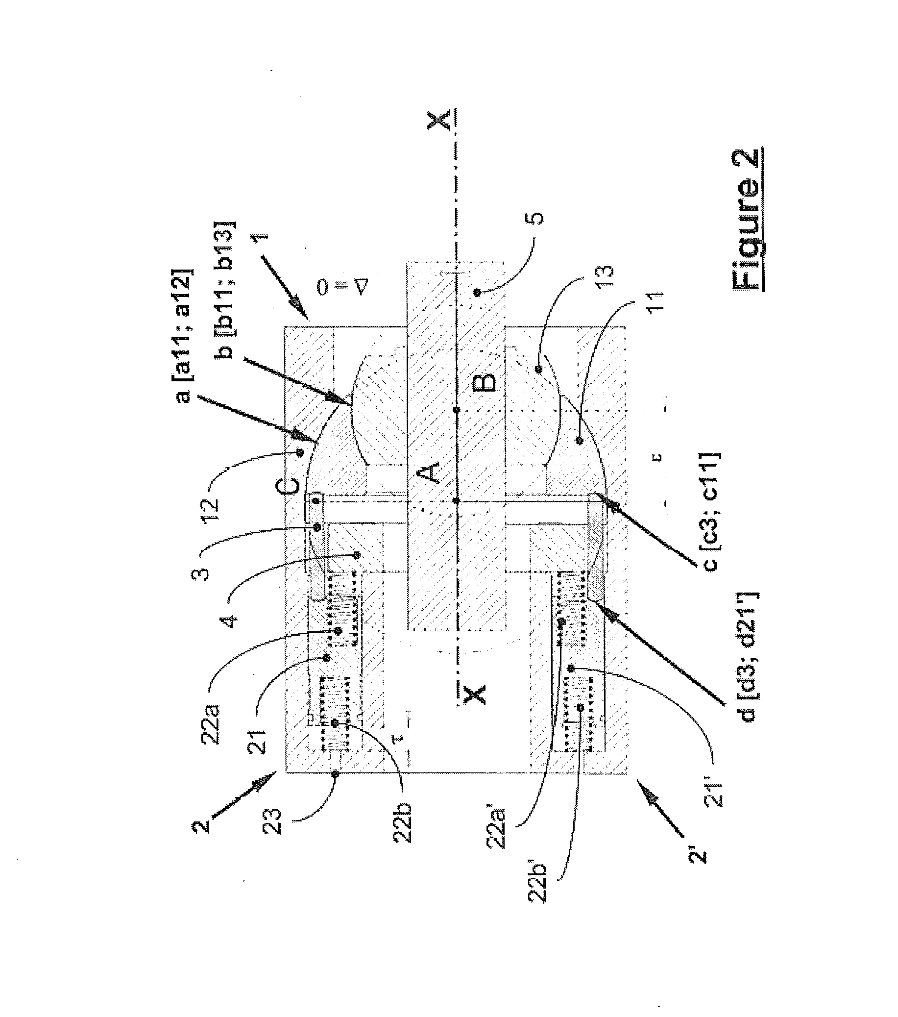
[0034]With reference to the drawings thus succinctly described, in particular to FIGS. 2-5, which illustrate the invention without limiting it in any way whatever, the system for the production of essentially radial displacements (in particular of the shaft 5 with respect to the frame 12) in one or two directions includes a device comprising a swivelling ring 11, an internal ring or ball joint 13, actuators 2, push rods 3, and a guide ring 4 for said push rods or compression rods.

[0035]In the bilateral device according to the invention, as defined above, the nested rings 11 and 13 are displaced under the action of the push rods 3 pushed by actuators 2 and / or 2′, and guided by a guide ring 4. Said nested rings are rotatable in their respective housings (a12) and (b11). It should be stated here that the housing for the ball joint 13 is included in the steerable swivelling ring 11; in other words, the convex surface of the ball joint connection (a) and the concave surface of the ball j...


PUM


Abstract

The invention relates to a device for generating essentially radial displacements and / or stresses of at least one mechanical part with respect to its X-X axis common with that of at least one other mechanical part functionally connected to the first one, said device comprising:(I) a frame, a swivelling ring (11) and an internal ring producing two nested ball joint connections (a) and (b) with respective centres A and B, eccentric by a distance or value ε along said X-X axis common to the two rings in a position said to be neutral,(II) one or more actuators in a barrel arrangement about the X-X axis for driving the mechanism, each actuator acting on the swivelling ring (11) via a guided push rod (3), and(III) a guide ring (4) for guiding the push rods (3) via a bidirectional planar link (e),while the swivelling rings (11, 13) are steerable by means of push rods (3) displaced by the actuators (2) and guided by the guide ring (4), andwhile said swivelling rings are rotatable in their respective housings (a) and (b),Application in particular for drilling trajectory control devices.

Description

TECHNOLOGICAL BACKGROUND[0001]1. Field of the Invention[0002]The present invention concerns the radial displacements of at least two mechanical parts adjacent to one another, in particular for steerable drilling applications. It concerns in particular drilling which requires accurate trajectory control, in particular in the fields of the petroleum and gas industry, civil engineering, geothermics and more generally in all fields of trenchless underground operations, or even the accurate steering of mechanical parts, such as rolling mill rollers, in particular.[0003]The invention concerns more particularly, whatever the application envisaged, an annular device providing for controlled essentially radial displacements and / or stresses between at least two mechanical parts with a common axis in one or two directions.[0004]2. Description of the Prior Art[0005]Drilling tool steering devices have been described for example in documents WO 90 / 07625, U.S. Pat. Nos. 6,581,699 and 2,898,935.[00...

Claims


Application Information

Patent Timeline
IPC IPC(8): E21B7/24E21B7/04
CPCE21B7/067
Inventor MILLET, FRANCOIS
Owner BREAKTHROUGH DESIGN
Learn More