
Battery Module

a battery module and battery technology, applied in the field of batteries, can solve problems such as damage to rechargeable batteries, and achieve the effect of stabilizing rechargeable batteries

Active Publication Date: 2012-02-16
ROBERT BOSCH GMBH +1
View PDF3 Cites 47 Cited by
  • Summary
  • Abstract
  • Description
  • Claims
  • Application Information

AI Technical Summary

Benefits of technology

[0010]Embodiments of the present invention provide a battery module that can stably fix rechargeable batteries.

Problems solved by technology

However, the rechargeable battery can be damaged due to external impact if the rechargeable battery is unstably fixed.

Method used


Image

  • Battery Module
  • Battery Module
  • Battery Module

Examples


Embodiment Construction

[0035]Embodiments of the present invention will be described more fully hereinafter with reference to the accompanying drawings, in which exemplary embodiments of the present invention are shown. As those skilled in the art would realize, the described embodiments may be modified in various different ways, all without departing from the spirit or scope of the present invention. Like reference numerals designate like elements throughout the specification and drawings.

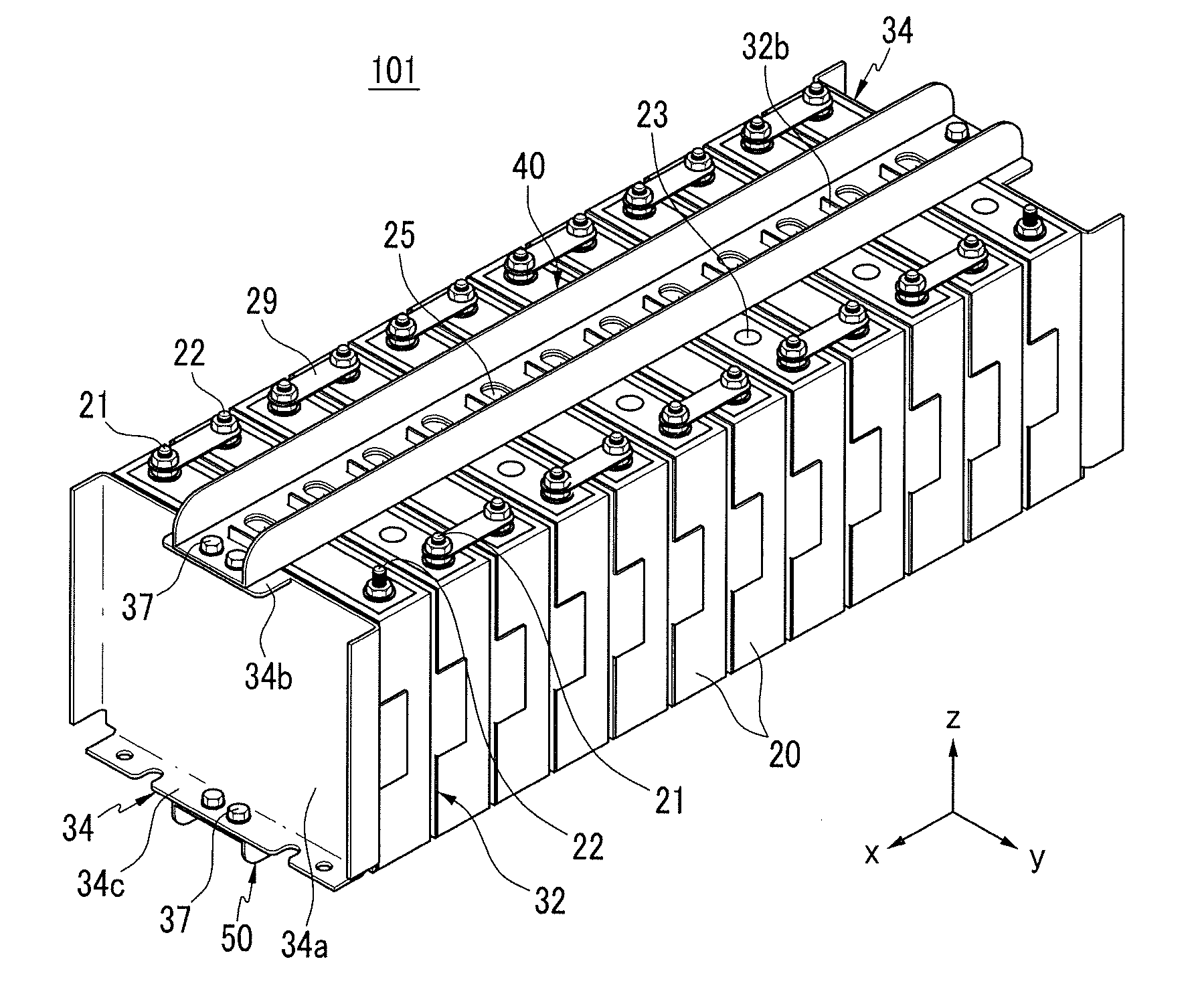
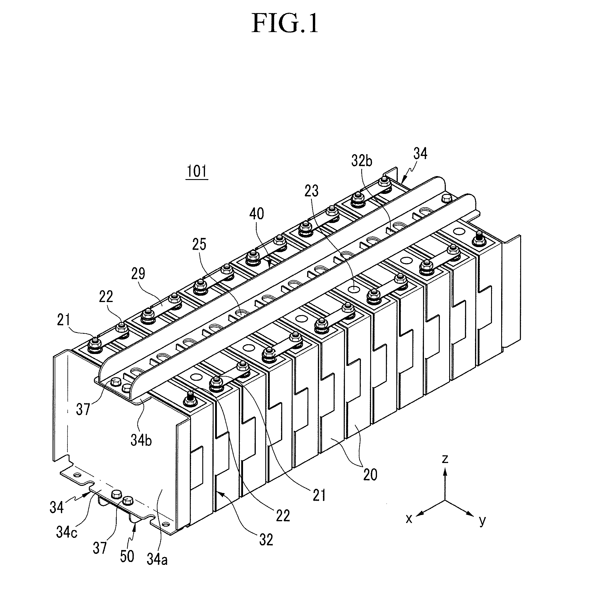
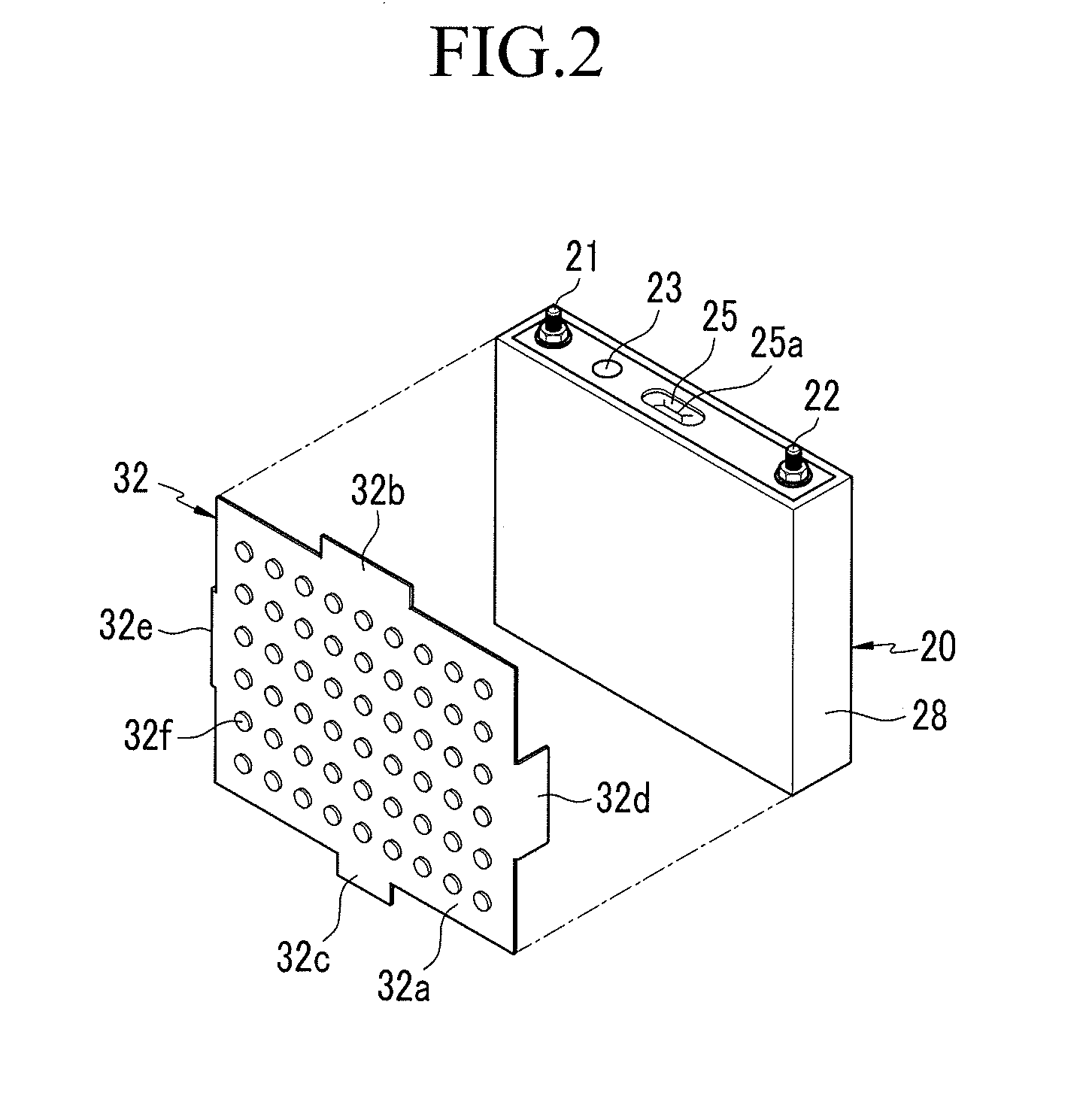
[0036]FIG. 1 is a perspective view of a battery module according to a first exemplary embodiment of the present invention, and FIG. 2 is a partially exploded perspective view of a rechargeable battery and a plate of the battery module according to the first exemplary embodiment of the present invention.

[0037]Referring to FIG. 1 and FIG. 2, a battery module 101 according to the first exemplary embodiment includes a plurality of rechargeable batteries 20, a plate 32 located between adjacent batteries of the plurality of re...


PUM


Abstract

A battery module includes a plurality of batteries stacked together; a plate between adjacent ones of the batteries, the plate comprising a plate body; and a connecting tab extending from an edge of the plate body; and a first connection member extending along the batteries, wherein the first connection member has a coupling portion through which the connecting tab extends.

Description

CROSS-REFERENCE TO RELATED APPLICATIONS[0001]This application claims priority to and the benefit of U.S. Provisional Application No. 61 / 372,299, filed on Aug. 10, 2010, in the United States Patent and Trademark Office, the disclosure of which is incorporated herein in its entirety by reference.BACKGROUND[0002]1. Field[0003]The present invention relates to a battery module having a plurality of batteries.[0004]2. Description of the Related Art[0005]A rechargeable battery differs from a primary battery in that it can be repeatedly charged and discharged, while the latter can only perform the irreversible conversion of chemical to electrical energy. A small-capacity rechargeable battery is used as the power supply for small electronic devices, such as cellular phones, notebook computers and camcorders, while a large-capacity rechargeable battery is used as the power supply for driving motors or the power storage battery in hybrid vehicles and the like.[0006]A large capacity high power ...

Claims


Application Information

Patent Timeline
IPC IPC(8): H01M10/50H01M2/24H01M50/209H01M50/264H01M50/291H01M50/529
CPCH01M2/1077H01M2/1083H01M10/0481H01M10/5059H01M10/5004H01M10/5016H01M10/5032H01M10/052H01M10/625H01M10/647H01M10/6557H01M10/613Y02E60/10H01M50/30Y02P70/50H01M50/291H01M50/209H01M50/264H01M50/50H01M50/543
Inventor KIM, MYUNG-CHULLEE, HYUN-YE
Owner ROBERT BOSCH GMBH
Learn More