Optical disc drive which can firmly fix the tray within the housing
- Summary
- Abstract
- Description
- Claims
- Application Information
AI Technical Summary
Benefits of technology
Problems solved by technology
Method used
Image
Examples
Embodiment Construction
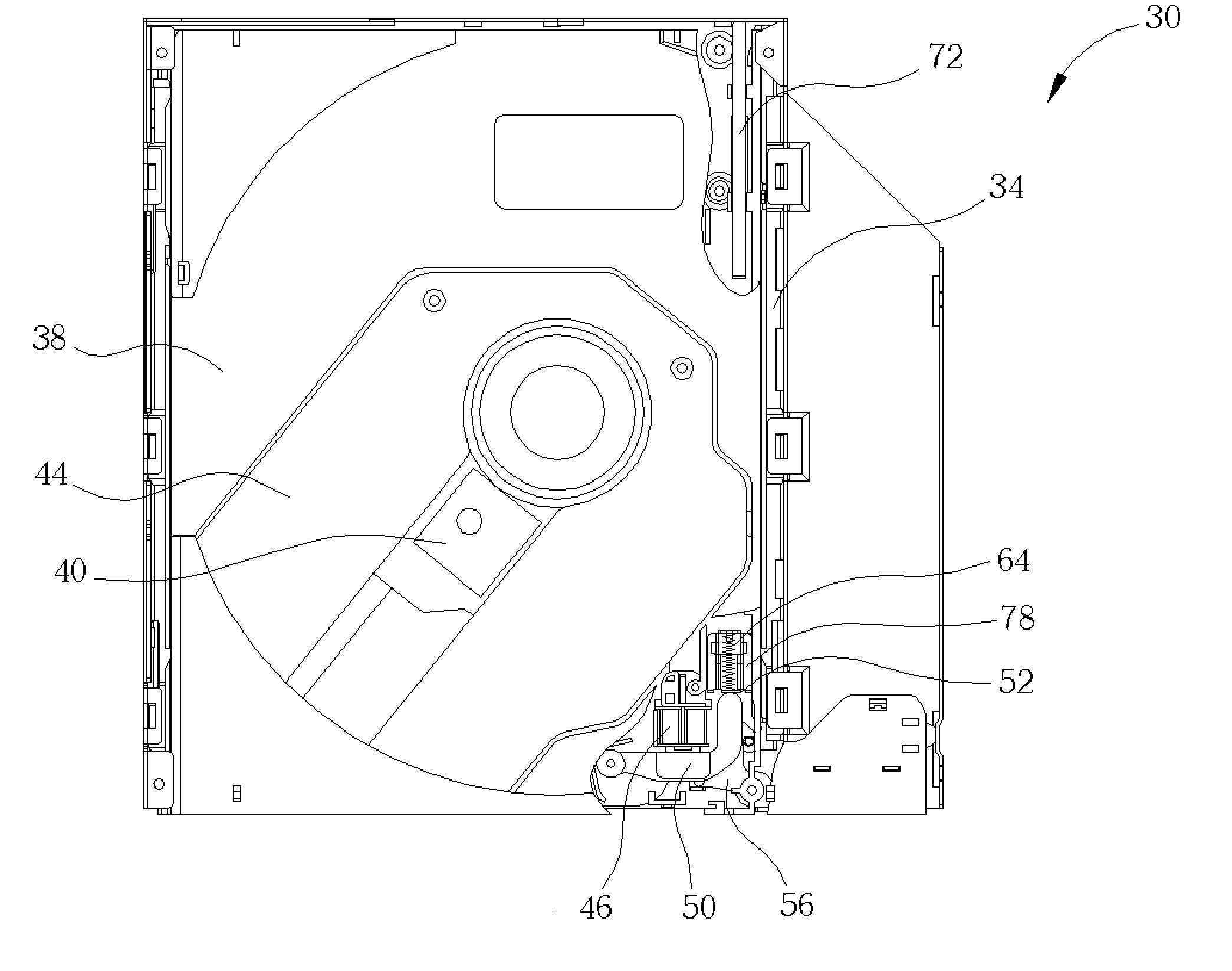
[0028] Please refer to FIG. 6-FIG. 11. FIG. 6 is a schematic diagram of a tray module 38 of an optical disc drive 30 that is in the tray-in location according to the present invention. FIG. 7 is a schematic diagram of a tray module 38 of the optical disc drive 30 in FIG. 6 that is withdrawn completely in the tray-out location. FIG. 8 is a full view of all components in the optical disc drive 30. FIG. 9 is a reverse diagram of some components when the tray module 38 of the optical disc drive 30 is in the tray-out location. FIG. 10 is a schematic diagram of an elastic device 52 in FIG. 8. FIG. 11 is a schematic diagram of a solenoid 46 and a latch 48 of the optical disc drive 30 in FIG. 8.
[0029] The optical disc drive 30 comprises a housing 32 having two tracks 34 and 36 and a tray module 38 movably installed in housing 32. The tray module 38 comprises a read / write module 40 for reading and writing the data in an optical disc, a tray 44 movably installed within the housing 32 along t...
PUM
 Abstract
Description
Claims
Application Information
 - R&D
- Intellectual Property
- Life Sciences
- Materials
- Tech Scout
- Unparalleled Data Quality
- Higher Quality Content
- 60% Fewer Hallucinations
Browse by: Latest US Patents, China's latest patents, Technical Efficacy Thesaurus, Application Domain, Technology Topic, Popular Technical Reports.
© 2025 PatSnap. All rights reserved.Legal|Privacy policy|Modern Slavery Act Transparency Statement|Sitemap|About US| Contact US: help@patsnap.com


