
Analysing radio network coverage

a radio network and antenna technology, applied in the field of data processing equipment, can solve the problems of high data collection volume, and high probability of data collection

Active Publication Date: 2012-02-16
AIRCOM INT
View PDF8 Cites 25 Cited by
  • Summary
  • Abstract
  • Description
  • Claims
  • Application Information

AI Technical Summary

Benefits of technology

"The present invention provides a method for analyzing the performance of a mobile radio network by using control messages from the network and a probe system to extract data from the network. The method can identify the relative distance of mobile terminals from the base station and the quality of data communication at that distance. This allows for a performance map to be generated without the need for physical sampling of the network. The invention can also be applied to any communications system where a probe system is employed. The technical effect of the invention is to provide a quantitative measure of network performance and quality of data communication in a mobile radio network."

Problems solved by technology

As will be appreciated, employing a technique in which an operator must drive a vehicle around a mobile radio network in order to establish a performance of that network is both time consuming and therefore expensive.
Due to the complexity of most modern mobile radio networks, the volume of data collected is usually very high, even if some form of filtering is applied to isolate a particular type of data which is then recorded.
For example, if a probe system were to be used to capture data relating to a particular coverage area even if a filter was applied such that only data pertaining to that coverage area was captured, the quantity of data that would be collected would be likely to be very great.
It is very difficult to manage, in a structured way, such large quantities of data.
It is particularly difficult to do so in a timely manner.

Method used


Image

  • Analysing radio network coverage
  • Analysing radio network coverage
  • Analysing radio network coverage

Examples


Embodiment Construction

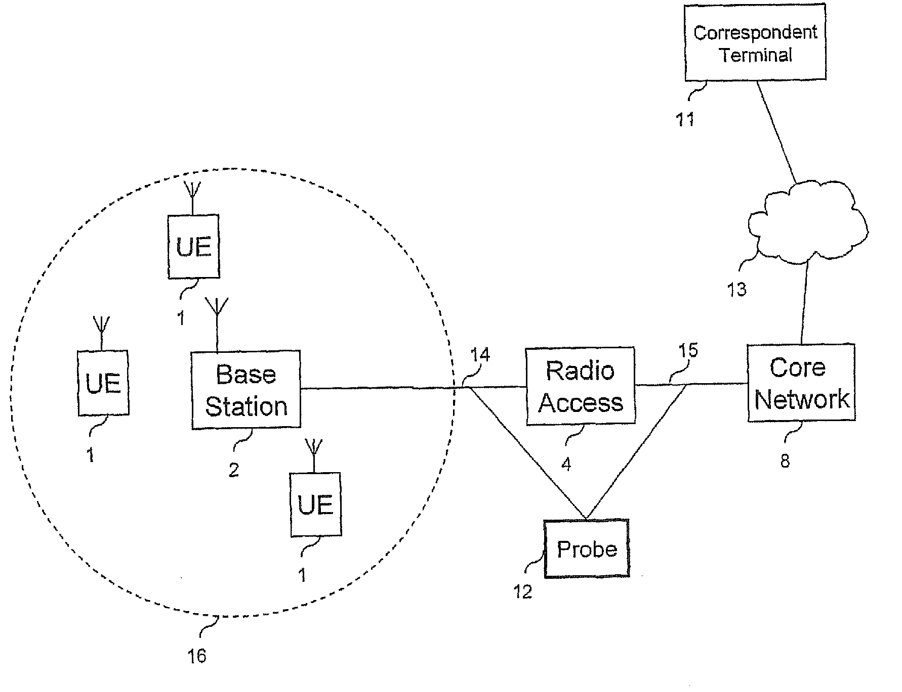
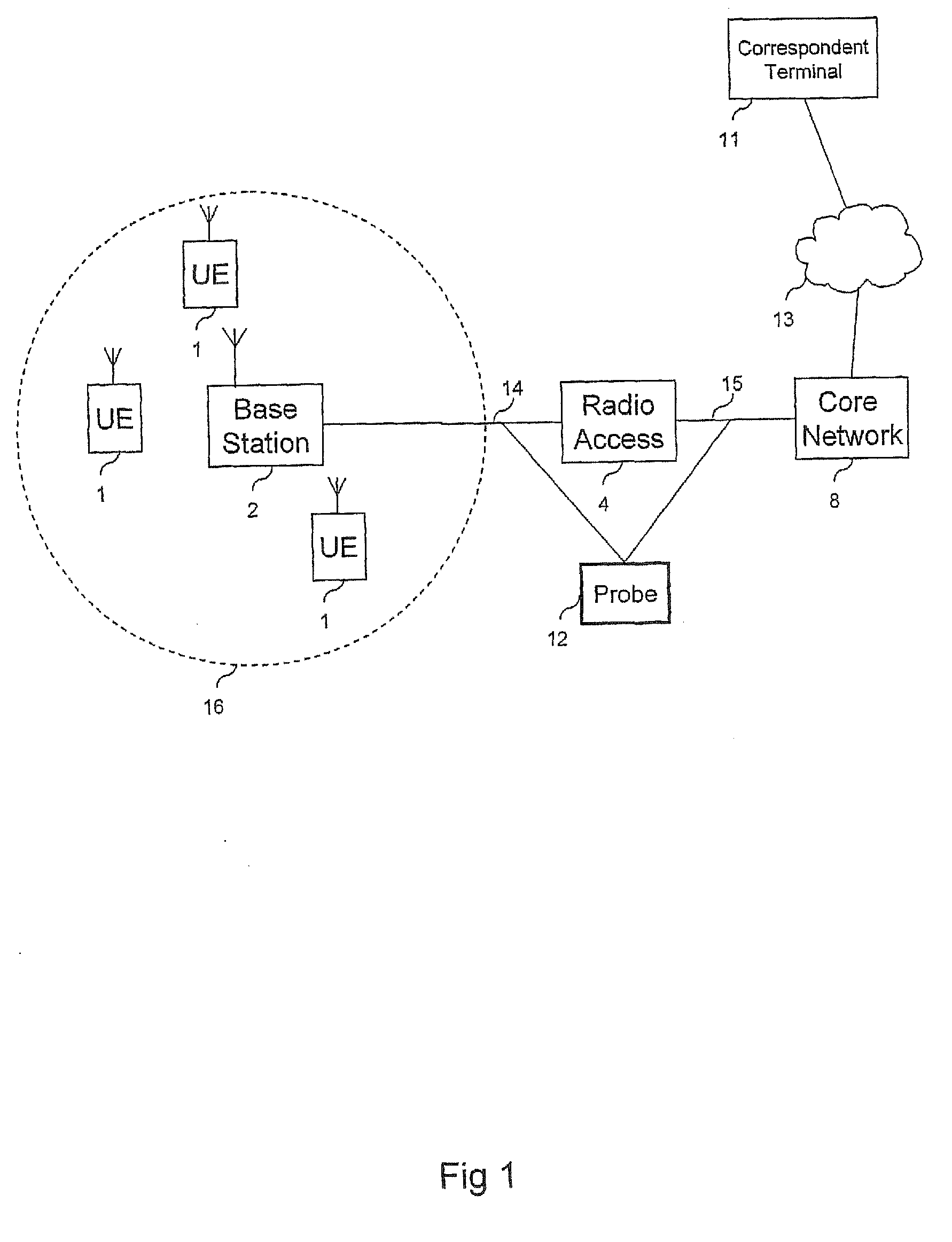
[0027]FIG. 1 provides a schematic block diagram of a generic mobile radio network. The mobile radio network includes a plurality of mobile terminals 1, a base station 2, a radio access controller 4 and a core network 8. A data analysing probe 12 is provided which is arranged to target and intercept data transmitted between components of the mobile radio network. FIG. 1 also shows a terminating terminal 11 connected to the core network 8 via an external network 13. The mobile radio network shown in FIG. 1 is a generic mobile radio network because the technique of the present invention can be applied to a number of different types of mobile radio networks. The mobile radio network could be operated in accordance with the global system for mobiles (GSM) in which case the base station 4 is more commonly referred to as a base transceiver station (BTS) and the radio access controller is referred to as a base station controller (BSC). Alternatively, the mobile radio network could be operat...


PUM


Abstract

A radio network coverage area provided by a mobile radio network is analysed. The analysis is provided by receiving control messages from a first interface communicated between a base station of the mobile radio network and a radio network controller, the control messages being provided for controlling the communications of the data to or from the mobile terminals via the base station. The method includes identifying a mobile identity number associated with the mobile terminal from the control messages communicated via the first interface, identifying, using the mobile identity number, mobility control messages communicated via the first interface, the mobility control messages providing an indication of a relative distance of the mobile terminal from the base station, receiving data communicated via a second interface between the radio network controller and a core network part of the mobile radio network, identifying the data communicated from the mobile terminal, using the mobile identity number identified from the first interface, determining a relative measure of quality of the data received from the mobile terminal, and generating a performance map providing a relative distance of the mobile terminal from the base station and a quality of data communicated at the relative distance from the mobile terminal.

Description

FIELD OF INVENTION[0001]The present invention relates to data processing apparatus for and methods of analysing a radio network coverage area provided by one or more base stations of a mobile radio network. The present invention also relates telecommunication systems and methods of communicating.BACKGROUND OF THE INVENTION[0002]Drive testing is a technique in which a vehicle which is equipped with a receiver is driven around a coverage area of a mobile radio network in order to generate a map of a relative performance of data communications within a radio coverage area provided by one or more base stations of the mobile radio network. The receiver is arranged to receive data in accordance with a wireless access interface specified for the mobile radio network concerned in order to determine a quality of the communicated data. The vehicle is driven by an operator throughout the coverage area of the mobile radio network in order to establish a map identifying a performance of the wire...

Claims


Application Information

Patent Timeline
Patent Type & Authority Applications(United States)
IPC IPC(8): H04W24/00
CPCH04W24/08H04W16/18
Inventor FOSTER, GERARD TERENCEGOETZ, IAN
Owner AIRCOM INT
Learn More