
System and method for optical measurement of a target

a target and optical measurement technology, applied in the field of system and a target optical measurement method, can solve the problems of high production cost of filters, inability to accurately measure requiring repeated measurements, and inability to accurately measure a target in a relatively long time, so as to achieve better light transmission, improve accuracy, and improve repeatability. the effect of the ra

Active Publication Date: 2012-02-16
TEKNOLOGIAN TUTKIMUSKESKUS VTT
View PDF3 Cites 19 Cited by
  • Summary
  • Abstract
  • Description
  • Claims
  • Application Information

AI Technical Summary

Benefits of technology

The present invention provides a new method for analyzing targets using a multi-wavelength laser spectroscopy technique called fabry-perot interferometry (FPI). Compared to existing methods, FPI has faster response times, greater repeatability, and improved accuracy and precision. Additionally, the invention uses high-speed electronics to control the changes in the FPI's pass band, making it easier to measure different wavelengths quickly. Furthermore, the invention eliminates the need for expensive mechanical components like filters and gratings, reducing costs while maintaining reliability and durability. Overall, the invention offers significant improvements over current techniques and enables applications previously limited due to cost or complexity.

Problems solved by technology

The technical problem addressed in this patent text is the limitations and disadvantages of current hyperspectral imaging instruments and the difficulties in optimizing the spectrum of the measurement according to the target. The text describes various solutions that have been developed to overcome these issues, but each has its own limitations and drawbacks. The patent text also describes a system for measuring fluorescence from a sample using a pneum well and a beam splitter mirror. The system includes a light source, excitation filters, and detectors for measuring the intensity of the fluorescence. The text also describes a method for measuring the position of the target using a filter wheel and a detector. The system has advantages and disadvantages depending on the specific application and the type of measurement.

Method used


Image

  • System and method for optical measurement of a target
  • System and method for optical measurement of a target
  • System and method for optical measurement of a target

Examples


Embodiment Construction

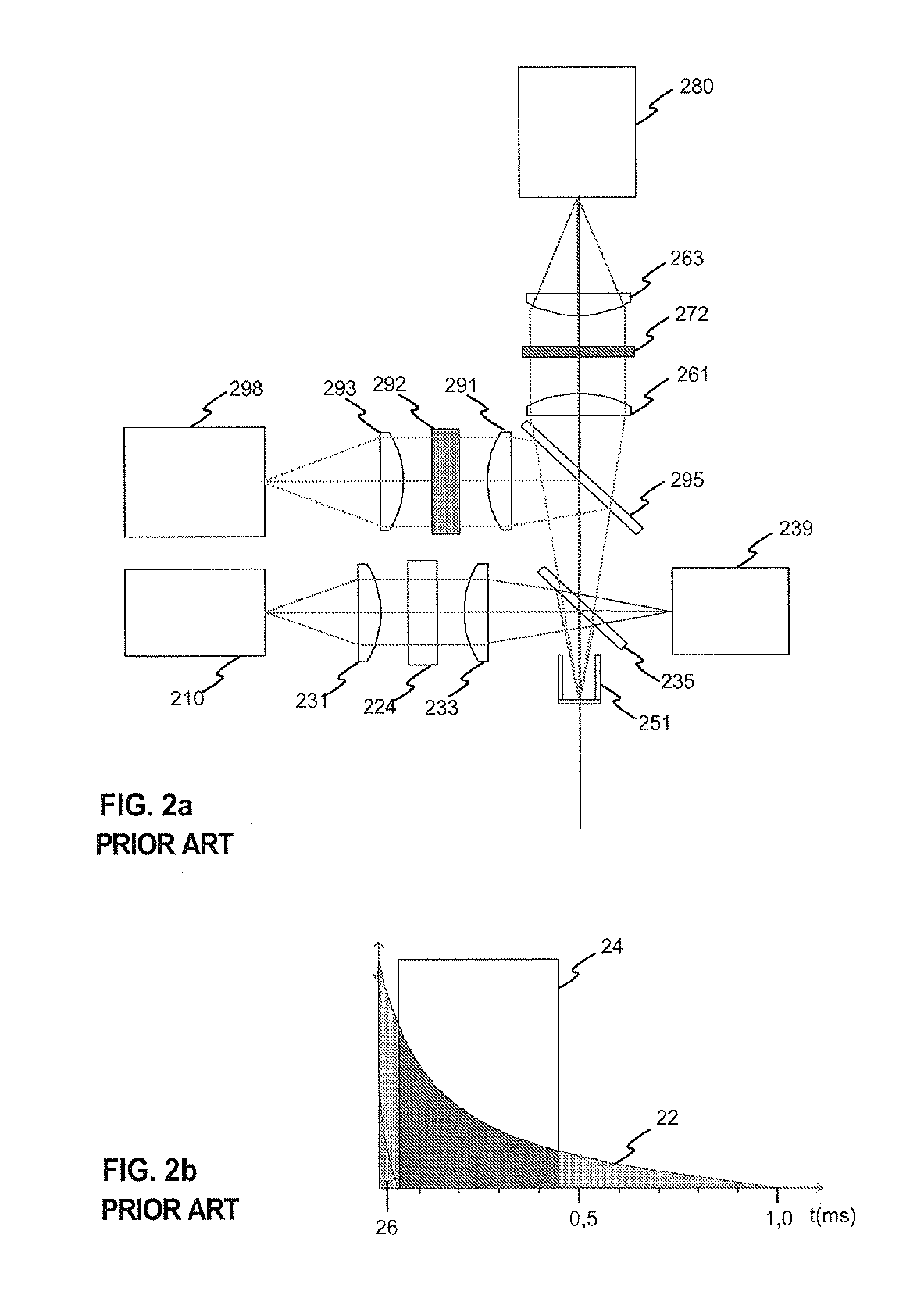
[0056]FIGS. 1, 2a and 2b were described in the prior art description above.

[0057]FIG. 3a illustrates an exemplary optical measurement system according to the invention, wherein controllable Fabry-Perot interferometers are used in alternated pass band and shutter modes at both illuminating path and measurement path in order to perform measurements with different successive wavelengths.

[0058]The system of FIG. 3a has a broadband light source 310, such as a halogen incandescent lamp. A light beam of the light source is collimated with lens 331 and led through a low pass filter 325 and a high pass filter 326. The purpose of the low pass and high pass filters is to serve as a pass band filter which determines the overall measurement range of wavelengths and substantially blocks light on wavelengths that are outside the operating area of the Fabry-Perot interferometers.

[0059]The illuminating light beam is further led through a first Fabry-Perot interferometer 341, which is controlled by f...


PUM


Abstract

The invention relates to a system and a method for optical measurement of a target, wherein the target is illuminated, either actively illuminated, reflecting ambient light, or self illuminating, and a measurement light beam received from the target or through it is detected. The prior art optical measurement systems generally include mechanical filter wheels and photomultiplier tubes, which cause the equipment to be expensive, large-sized and often not sufficiently accurate and stable. The objective of the invention is achieved with a solution, in which the illuminating light beam and/or measurement light beam is led through a Fabry-Perot interferometer or a set of two or more Fabry-Perot Interferometers, and the Fabry-Perot interferometer or a set of two or more Fabry-Perot Interferometers is controlled into different modes during the measurement of a single target. The invention can be applied in optical measurements where, for example, reflectance, absorption of fluorescence of the target is measured.

Description


Claims


Application Information

Patent Timeline
Owner TEKNOLOGIAN TUTKIMUSKESKUS VTT
Learn More