
Ophthalmologic observation and photographing apparatus

a technology which is applied in the field of ophthalmologic observation and photographing equipment, can solve the problems of inability to obtain optimum fundus image, inability to check the fundus region hidden by the index, and inability to obtain exact alignmen

Inactive Publication Date: 2012-02-16
CANON KK
View PDF2 Cites 5 Cited by
  • Summary
  • Abstract
  • Description
  • Claims
  • Application Information

AI Technical Summary

Benefits of technology

[0011]The present invention is directed to an ophthalmologic observation and photographing apparatus which can perform position adjustment using an alignment index in visible fluorescence photography, and remove or attenuate the index when a moving image is stored or reproduced, so that a diagnosis of an ocular fundus region can be performed without being hidden by the index.

Problems solved by technology

Thus, when a circulation state of the fluorescent agent is recorded as a moving image, the alignment index is photographed superposed on the fundus image, and a problem that a fundus region hidden by the index cannot be checked may occur.
Therefore, there is a problem that exact alignment may not be gained due to a skill of the photographer, and an optimum fundus image cannot be obtained.
In conventional photographing of visible fluorescence moving images, if a moving image is taken without projecting an alignment index for position adjustment to a fundus, there is a problem that a fundus image of good quality cannot be obtained due to difficulty in alignment.

Method used


Image

  • Ophthalmologic observation and photographing apparatus
  • Ophthalmologic observation and photographing apparatus
  • Ophthalmologic observation and photographing apparatus

Examples


example 1

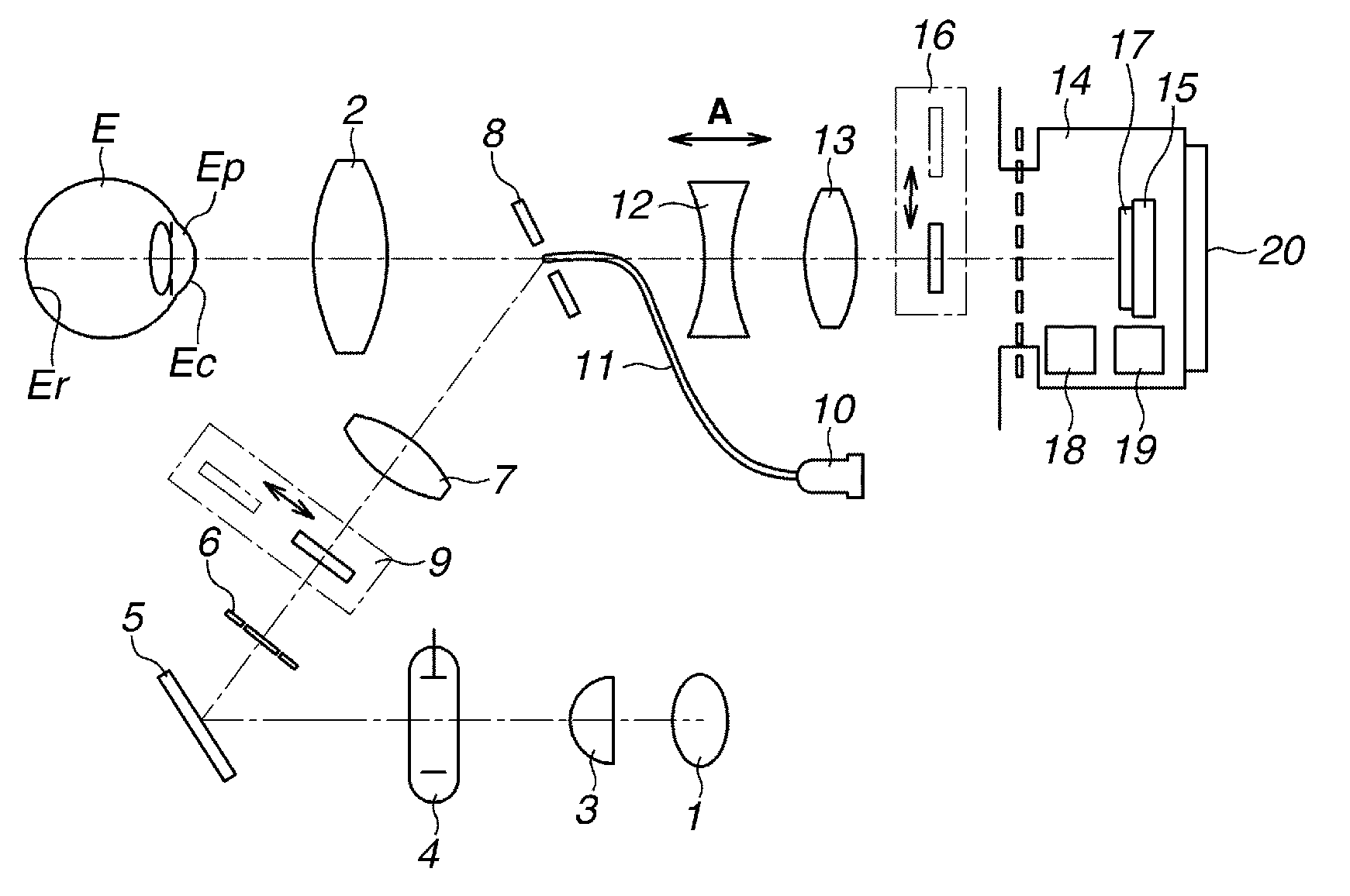
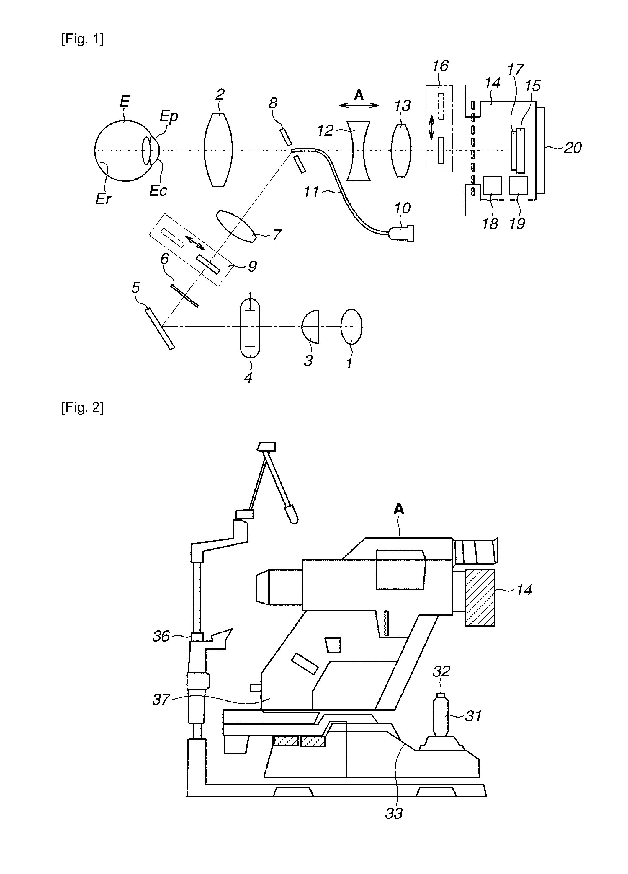
[0033]FIG. 1 illustrates a configuration of a fundus camera used in ophthalmologic observation photography according to an exemplary embodiment of the present invention. On an optical path from an observation light source 1 to an objective lens 2 placed in front of a subject's eye E, a condenser lens 3, a photographic light source 4, a mirror 5, a diaphragm 6 with a ring-shaped opening, a relay lens 7, and a perforated mirror 8 are arranged in this order. Further, an exciter filter 9 for visible fluorescence is insertably and retractably arranged between the diaphragm 6 and the relay lens 7. By those devices, a fundus illumination optical system is configured.

[0034]In a hole of the perforated mirror 8, an alignment index light source 10 for projecting an alignment index to a cornea Ep of a subject's eye is arranged via two exit ends of an optical fiber 11. On the optical path in a direction passing through the perforated mirror 8, a focusing lens 12, a photographic lens 13, and a si...


PUM


Abstract

An ophthalmologic observation and photographing apparatus capable of photographing a color image and a fluorescence image includes an illumination unit for illuminating a fundus of a subject's eye, an observation and photographing unit for observing and photographing a specified region of the illuminated subject's eye, a barrier filter insertably mounted to the observation and photographing unit and configured to transmit a fluorescence wavelength range and block excitation light, a color photographing unit including a tri-color separation filter and mounted in the observation and photographing unit, and an index projecting unit for projecting an index light to be photographed by superimposing on an image of the specified region of the subject's eye. The index light passes through the barrier filter, includes a wavelength range different from the fluorescence wavelength range, and can pass through a filter having a wavelength range different from a filter which transmits fluorescence through the most among the tri-color separation filter.

Description

TECHNICAL FIELD[0001]The present invention relates to an ophthalmologic observation and photographing apparatus which is used in ophthalmological clinics and group health examination, for example.BACKGROUND ART[0002]A fundus camera is known as an ophthalmologic photographing apparatus. In photography using a general fundus camera, general color photographing and fluorescence photography using a fluorescent agent injected into a vein of an examinee are well known.[0003]In fluorescence photography, light to illuminate an ocular fundus, only a specific wavelength is required to excite a fluorescent agent and wavelength of the light other than the specific wavelength are not necessary. Therefore, the fundus camera includes a bandpass filter arranged in an illumination system optical path to prevent unnecessary light from reaching the ocular fundus of a subject's eye. At the same time, a filter that transmits only a fluorescence wavelength is arranged on a photographing system optical pa...

Claims


Application Information

Patent Timeline
Patent Type & Authority Applications(United States)
IPC IPC(8): A61B3/15
CPCA61B3/1241A61B3/14
Inventor DOBASHI, YASUHIROOKUMURA, TOSHIAKI
Owner CANON KK
Learn More