
Method for detecting a developing torque for a hybrid drive

a technology of hybrid drive and developing torque, which is applied in the direction of mechanical equipment, transportation and packaging, instruments, etc., can solve the problems of inability to accurately detect the developing torque of the separating clutch kb>0/b>, and take approximately 3 s to 10 s until the developing torque, etc., to achieve shorten the time, the effect of being exposed to even greater loads and shortening the tim

Inactive Publication Date: 2012-02-09
ROBERT BOSCH GMBH
View PDF31 Cites 6 Cited by
  • Summary
  • Abstract
  • Description
  • Claims
  • Application Information

AI Technical Summary

Benefits of technology

[0008]As a function of the predefined engaged position, the electric motor torque may be increased by a predefined torque, so that the developing torque may be detected in a targeted and pointed manner. Furthermore, it is possible to disengage the separating clutch again after each time it is engaged during the detection operation, thereby shortening the time during which the separating clutch is in a slip state. In contrast with that, the separating clutch is linearly engaged according to conventional methods for the entire duration of detection, for example, and is thereby exposed to even greater loads.
[0009]It is also advantageous that a shorter period of time is needed for the renewed determination of the developing torque. Furthermore, the separating clutch is under lower thermal and mechanical loads, so that clutch wear is reduced on the whole. Furthermore, a determination of the developing torque is also possible at higher torques of the separating clutch, so that a higher detection accuracy is achieved. Furthermore, a characteristic curve may also be recorded at differently high torques, thereby avoiding the disadvantage that calculation of the characteristic curve is possible only on the basis of measurements in the low torque range. According to the present invention, the developing torque may also be detected at comparatively low rotational speeds because in contrast with an internal combustion engine, the electric motor applies a high torque even at lower rotational speeds. Due to the lower mechanical clutch load, lower clutch wear and thus a lower clutch temperature are also to be expected. In addition, the concept according to the present invention is accurate because system influences such as noise, for example, do not enter into the calculation.
[0013]According to one specific embodiment, the first drive unit is operated at a predefined rotational speed before the separating clutch is brought into the predefined engaged position at a predefined rotational speed, and the torque of the first drive unit is changed after the separating clutch is brought into the predefined engaged position in such a way that a constant rotational speed of the first drive unit is established. The additional torque to be applied to ensure a constant rotational speed of the first drive unit may therefore be detected in an advantageous manner.
[0015]According to one specific embodiment, the value of the predefined torque is increased when, after the separating clutch is brought into the predefined engaged position, the rotational speed of the first drive unit is reduced. The value of the predefined torque is reduced when, after the separating clutch is brought into the predefined engaged position, the rotational speed of the first drive unit is increased. Thus a simple method of detecting the predefined torque is performed in an advantageous manner.

Problems solved by technology

One disadvantage of the method described above is that it may take approximately 3 s to 10 s until the developing torque has been detected during engagement of separating clutch K0.
In addition, another disadvantage is that separating clutch K0, which is in the slip state for a longer period of time, must withstand higher torques, and it may thus be damaged.
For this reason, this method is performed in a mechanically unstable range, so that the developing torque during engagement of separating clutch K0 cannot be detected accurately.
The developing torque may also include mechanical loss, for example, wear on the clutch disks, a rise in temperature and / or inertia, etc.
In contrast with that, the separating clutch is linearly engaged according to conventional methods for the entire duration of detection, for example, and is thereby exposed to even greater loads.

Method used


Image

  • Method for detecting a developing torque for a hybrid drive
  • Method for detecting a developing torque for a hybrid drive
  • Method for detecting a developing torque for a hybrid drive

Examples


Embodiment Construction

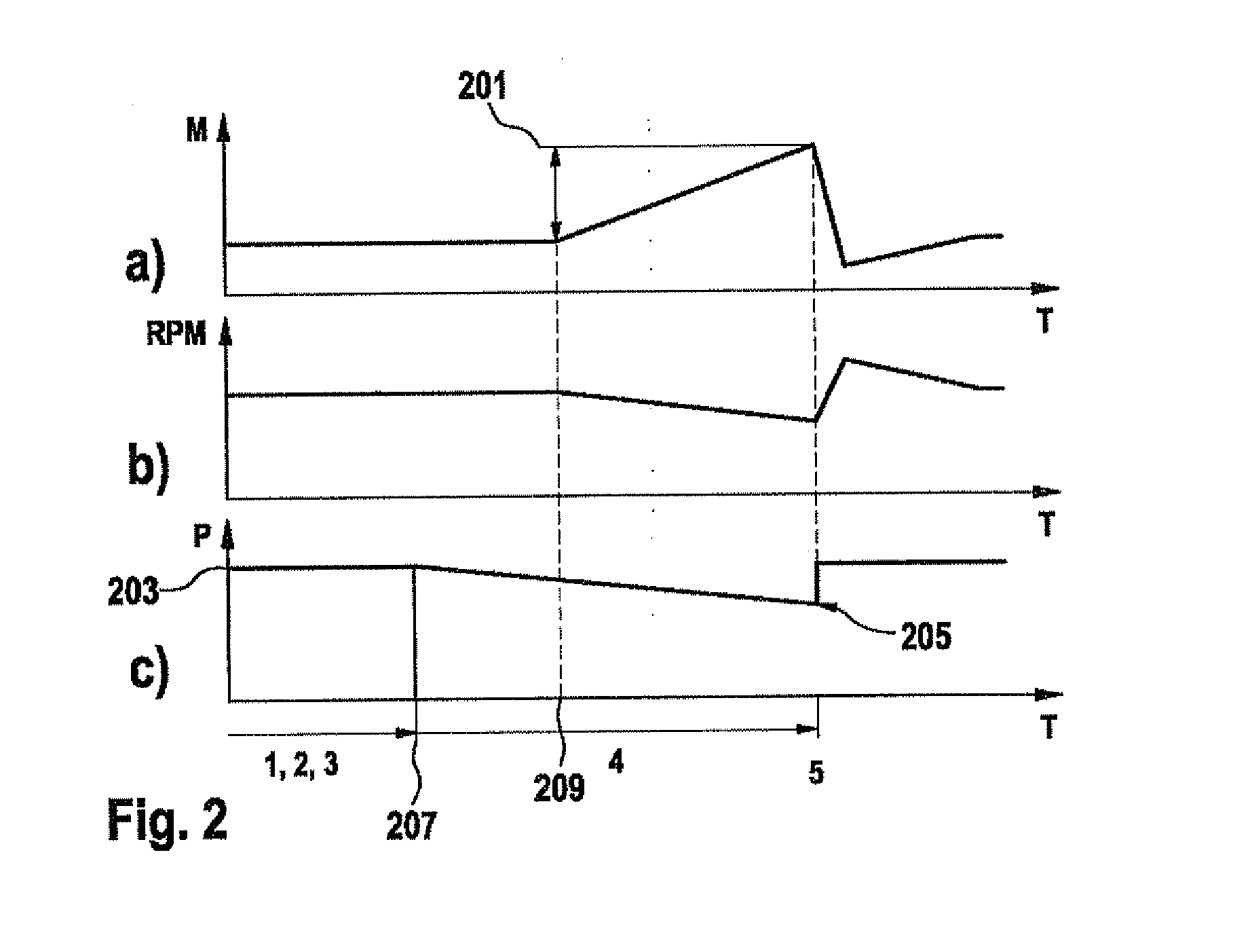
[0027]FIG. 3 shows a time diagram of an example method for detecting a developing torque in an engaged position of a separating clutch K0 illustrated in FIG. 1, for example. FIG. 3a shows a curve of a torque generated by an electric motor as a function of time; FIG. 3b shows a curve of a rotational speed of the electric motor as a function of time, and FIG. 3c shows a curve of a state P of separating clutch K0, which may have a disengaged state, an engaged state and a slip state, as a function of time.

[0028]For executing the example method, internal combustion engine ICE is shut off and separating clutch K0 is disengaged. Separating clutch K0 remains disengaged up to a point in time 301, while the electric motor torque is kept constant. The transmission of the hybrid vehicle may be locked in the park position, for example. Furthermore, the rotational speed of the electric motor is kept constant at 500 rpm by a speed regulator, for example. At point in time 301, separating clutch K0 ...


PUM

PropertyMeasurementUnit
torqueaaaaaaaaaa
rotational speedaaaaaaaaaa
transfer torqueaaaaaaaaaa

Abstract

A method for detecting a developing torque for a hybrid drive, the hybrid drive having a first drive unit, in particular an electric motor, and a second drive unit, in particular an internal combustion engine, the drive units being coupleable with the aid of a separating clutch, wherein the separating clutch is brought into a predefined engaged position, the torque of the first drive unit is changed, and the developing torque is detected at the predefined engaged position as a function of the change in the torque of the first drive unit.

Description

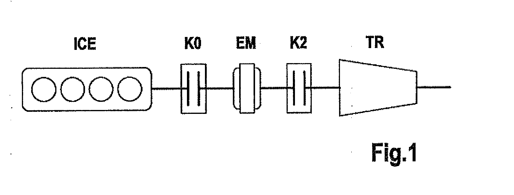
FIELD OF THE INVENTION[0001]The present invention relates to the field of separating clutches in hybrid vehicles.BACKGROUND INFORMATION[0002]FIG. 1 shows as an example a hybrid drive having an internal combustion engine ICE, a separating clutch K0, an electric motor EM, another separating clutch K2 and a transmission module TR. Separating clutch K0 is provided to separate internal combustion engine ICE from the drive train or to connect it thereto again. Thus, for example, in a purely electric motor drive using electric motor EM as the drive source, separating clutch K0 is disengaged and internal combustion engine ICE is shut down. In a transition from an electric motor drive to a hybrid drive in which both electric motor EM and internal combustion engine ICE are used as drive sources, internal combustion engine ICE may first be driven mechanically by separating clutch K0 to achieve a predefined rotational speed, for example. Separating clutch K0 is operated in a slip state in which...

Claims


Application Information

Patent Timeline
Patent Type & Authority Applications(United States)
IPC IPC(8): G01L3/00
CPCB60K6/48Y02T10/642B60L2240/423B60L2240/443B60W10/02B60W10/08B60W20/00B60W2510/0225B60W2510/0275B60W2510/0657B60W2510/083B60W2710/022B60W2710/025B60W2710/027B60W2710/081B60W2710/083Y02T10/56Y02T10/6221B60L2240/421Y02T10/62Y02T10/64B60W2050/0031B60W20/40Y02T10/40
Inventor SAKUTA, KAZUMASA
Owner ROBERT BOSCH GMBH
Learn More