
Power Supply control Apparatus and Method Thereof and Mobile Apparatus Using the same

a control apparatus and power supply technology, applied in power management, high-level techniques, instruments, etc., can solve the problems of weak power from the wireless signal of the nfc reader, rather limited power obtained by the nfc chip b>230/b> from the wireless signal, and extremely limited battery power of the mobile phone b>20/b>, so as to reduce power consumption

Active Publication Date: 2012-02-02
XUESHAN TECH INC
View PDF7 Cites 87 Cited by
  • Summary
  • Abstract
  • Description
  • Claims
  • Application Information

AI Technical Summary

Benefits of technology

[0017]One object of the present invention is to provide an electronic power supply control apparatus and method thereof applied to a communication apparatus. Accordingly, through controlling a switch to determine whether to provide power from a battery of a mobile apparatus to the communication apparatus, the mobile apparatus maintains a power-saving mode when electronic payment is not performed to achieve an object of reducing power consumption.
[0021]According to a power supply control apparatus and method thereof applied to a communication apparatus provided by the present invention, power is only provided to the communication apparatus when a communication function is performed to reduce power consumption of a battery of a mobile apparatus thereby achieving an object of increasing a standby time of the mobile apparatus.

Problems solved by technology

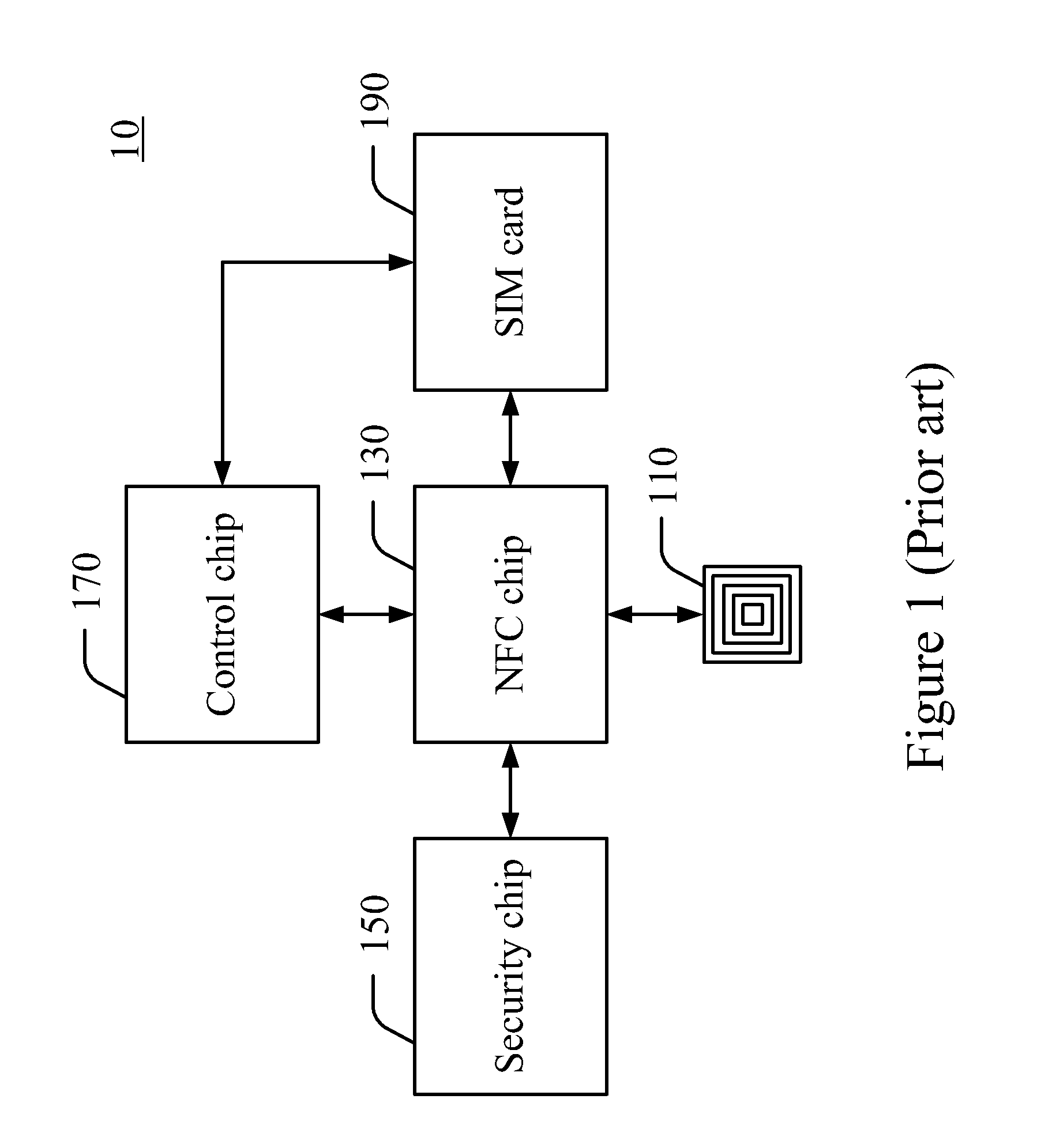
For example, when the mobile phone 10 is set to function as a transportation ticket, a problem occurs during the electronic payment identification procedure when the battery of the mobile phone 10 cannot supply power.
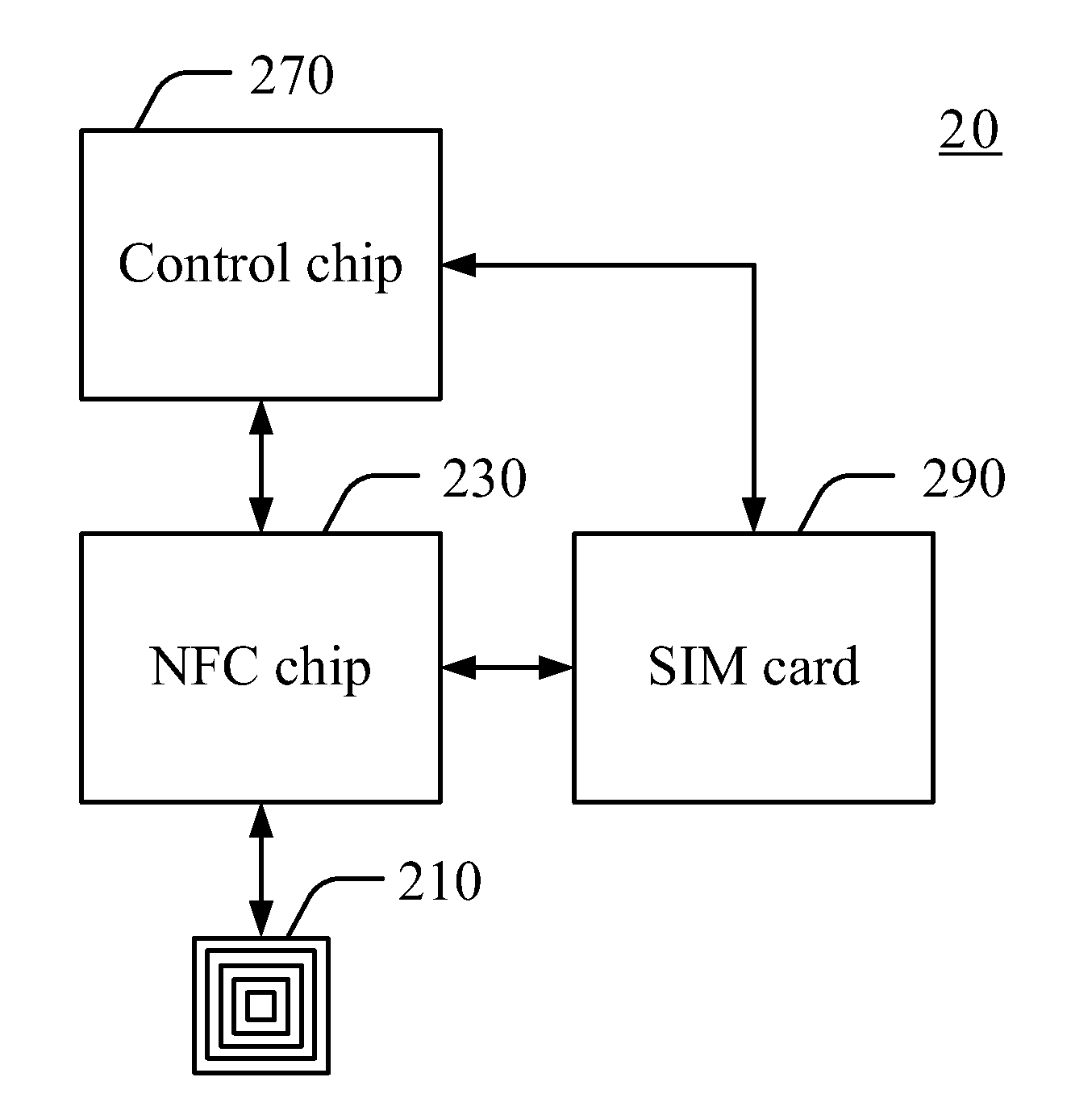
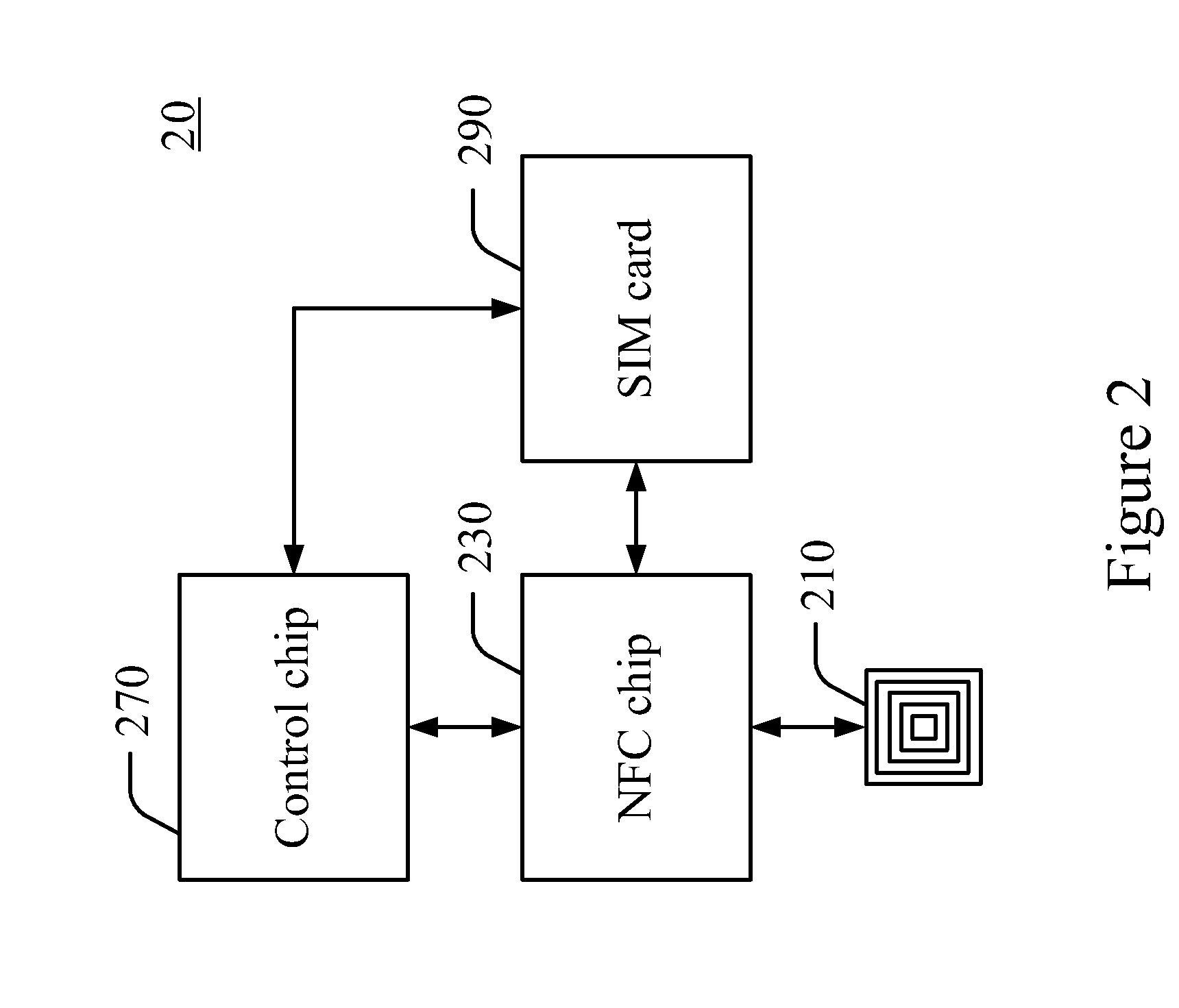
However, since power from the wireless signal from the NFC reader may be weak, power obtained by the NFC chip 230 from the wireless signal is rather limited; a rather short communication distance is required between the NFC chip 230 and the NFC reader when electronic power for operating the NFC chip 230 is only provided from the wireless signal.
However, battery power of the mobile phone 20 is extremely limited, and standby time of the mobile phone 20 is seriously limited because of power consumption of the NFC 230, which is a significant disadvantage for a power-saving mobile apparatus.

Method used


Image

  • Power Supply control Apparatus and Method Thereof and Mobile Apparatus Using the same
  • Power Supply control Apparatus and Method Thereof and Mobile Apparatus Using the same
  • Power Supply control Apparatus and Method Thereof and Mobile Apparatus Using the same

Examples


Embodiment Construction

[0030]In order to solve the power-consumption problem of the NFC apparatus of the conventional mobile apparatus, the power control apparatus according to one embodiment of the present invention includes a switch configured between a battery of a mobile device and an NFC device. When no wireless signal of an NFC reader is detected, the power supply control apparatus turns off the switch to stop providing power from the battery of the mobile apparatus to the NFC device. Upon detecting the wireless signal transmitted from the NFC reader, the power supply control apparatus turns on the switch to provide power from the battery of the mobile apparatus to the NFC device.

[0031]FIG. 3 is a block diagram of functions of a power supply control apparatus applied to a communication device in accordance with a first embodiment of the present invention. A power supply control apparatus 310 comprises a signal detecting unit 320 and a switch 340. FIG. 4 is a flow chart of a power supply control meth...


PUM


Abstract

A power supply control apparatus is applied to a communication apparatus that is applied to a mobile apparatus. The power supply control apparatus includes a switch, coupled between the communication apparatus and a power supply; and a signal detecting unit, for detecting a wireless signal via an electromagnetic introduction approach to correspondingly generate a detection signal. It is determined whether to provide power to the communication apparatus via the switch according to the detection signal.

Description

CROSS REFERENCE TO RELATED PATENT APPLICATION[0001]This patent application is based on Taiwan, R.O.C. patent application No. 099124926 filed on Jul. 28, 2010.FIELD OF THE INVENTION[0002]The present invention relates to a power supply control apparatus and method thereof, and more particularly, to a power supply control apparatus and method thereof applied to a communication apparatus.BACKGROUND OF THE INVENTION[0003]After decades of development, contactless chip cards are widely used everywhere in daily lives, such as transportation, security control and electronic payment. Moreover, because of the widespread use of contactless chip cards in the fields of rapid transit, logistic management, product authentication and identification, the contactless chip card technology continuously develops and becomes more diversified. Likewise, mobile devices which are multifunctional become indispensible in daily lives. Specifically, there is a trend to allow mobile communication devices to integ...

Claims


Application Information

Patent Timeline
IPC IPC(8): H04B5/00G06K7/01
CPCG06K19/0705H04B5/0062H04W52/0274H04W52/0229H04B5/0081Y02D30/70H04B5/77H04B5/26
Inventor CHEN, CHIEN-SHENGCHIANG, CHIEN-SHAN
Owner XUESHAN TECH INC
Learn More