
Hybrid photovoltaic cells and related methods

a photovoltaic cell and hybrid technology, applied in the field of solar cells, can solve the problems of increasing material costs, inflexible and expensive, excitons are very short-lived, and can only travel about 10 nm before recombining, and achieves the effects of reducing recombination losses, mechanical flexibility, and high conversion efficiency of photons into electricity

Inactive Publication Date: 2012-02-02
NANOCO TECH LTD
View PDF33 Cites 1 Cited by
  • Summary
  • Abstract
  • Description
  • Claims
  • Application Information

AI Technical Summary

Benefits of technology

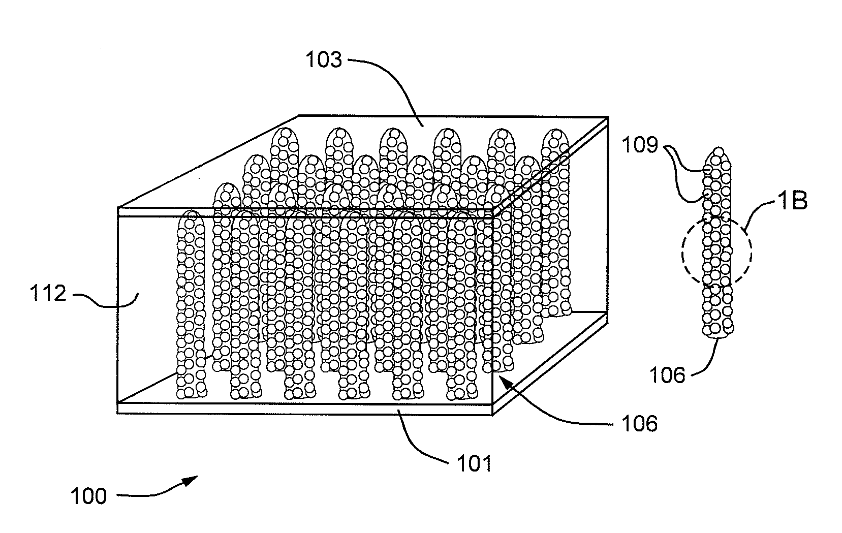
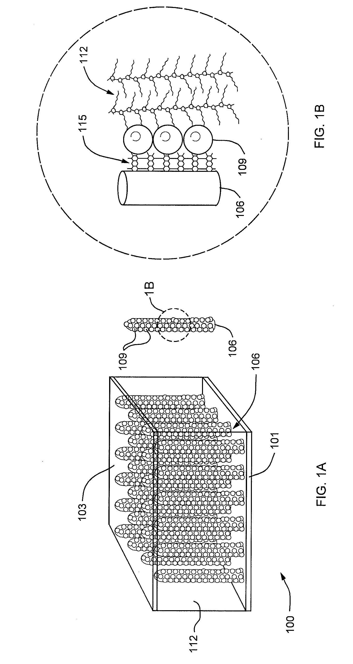
[0027]One of the advantages of the invention lies in the use of small particles, the nanocrystals, as both light absorber and heterojunction. The resulting spatio-temporal proximity of exciton generation and splitting entails a significant reduction in recombination losses, compared, for example, with those of conventional polymer PV cells, and consequently in higher conversion efficiencies of photons into electricity. Embodiments of the invention offer the additional advantages of mechanical flexibility and low cost manufacturing processes.

Problems solved by technology

Creation of p-n junctions generally involves high-temperature processing in inert atmospheres to form very pure, crystalline silicon wafers, which are inflexible and expensive.
Because silicon is an indirect semiconductor, a relatively thick layer is typically needed to achieve a good level of absorption, which increases material costs further.
Unfortunately, excitons are very short-lived and can only travel about 10 nm before recombining.
Hence, any photon absorbed more than this diffusion length away from a heterojunction will be wasted.
There is no band-bending, so splitting of the exciton is more difficult.
The lack of selectivity at the electrode towards one particle or another means that the electrodes can make contact with both the donor and acceptor species.
For example, a bi-layer structure in which each layer has only one component results in a cell with poor performance.
The reason is that the lifetime of the excited state of the light-absorbing polymer is generally shorter than the transfer rate of the exciton to the interface, and, consequently, the majority of the excitons formed in the bulk of the polymer never reach the interface separating electrons and holes, resulting in loss of photocurrent.
This technology shows promise, but there are obstacles to overcome.
One problem is incomplete absorption of the incident radiation.
The polymer—which absorbs light very strongly and is referred to as a polymeric dye—has a large extinction coefficient (>100,000 M−1 cm−1), but due to low exciton migration rates, the films must generally be thinner than 100 nm, which contributes significantly to incomplete absorption.
A problem associated with the light-absorbing polymer strategy is underutilization of available solar energy due to the narrow absorption bandwidth of typical polymers.
Unfortunately, it is difficult to disperse inorganic nanocrystals into a solution of monomers.
Ruthenium dye-sensitized, nanorod-based DSSCs tend to exhibit low efficiency, however, because the lower surface area does not accommodate enough dye to absorb all of the incident light.

Method used


Image

  • Hybrid photovoltaic cells and related methods
  • Hybrid photovoltaic cells and related methods
  • Hybrid photovoltaic cells and related methods

Examples


example 1

[0047]Cu(I) acetate (1 mmol) and In(III) acetate (1 mmol) are added to a clean and dry RB-flask. Octadecene ODE (5 mL) is added the reaction mixture heated at 100° C. under vacuum for 30 mins. The flask is back-filled with nitrogen and the temperature raised to 140° C. 1-octane selenol is injected and the temperature falls to 120° C. The resulting orange suspension is heated with stirring and a transparent orange / red solution is obtained when the temperature has reached 140° C. This temperature is maintained for 30 minutes, then 1M tri-octyl-phoshine selenide TOPSe (2 mL, 2 mmol) is added dropwise and the solution heated at 160° C. The PL is monitored until it reaches the desired wavelength, after which it is cooled and the resulting oil washed with methanol / acetone (2:1) 4-5 times and finally isolated by precipitation with acetone.

example 2

Large Scale Production

[0048]A stock solution of TOPSe was prepared by dissolving Se powder (10.9, 138 mmol) in TOP (60 mL) under nitrogen. To dry, degassed ODE was added Cu(I) acetate (7.89 g, 64.4 mmol) and In(III) acetate (20.0 g, 68.5 mmol). The reaction vessel was evacuated and heated at 140° C. for 10 min, backfilled with N2 and cooled to room temp. 1-Octane selenol (200 mL) was added to produce a bright orange suspension. The temperature of the flask was raised to 140° C. and acetic acid distilled from the reaction at 120° C. On reaching 140° C. the TOPSe solution was added dropwise over the course of 1 hour. After 3 hours the temperature was raised to 160° C. The progress of the reaction was monitored by taking aliquots from the reaction periodically and measuring the UV / Visible and photoluminescence spectra. After 7 hours the reaction was cooled to room temperature and the resulting black oil washed with methanol. Methanol washing was continued until it was possible to preci...


PUM

PropertyMeasurementUnit
sizeaaaaaaaaaa
diameteraaaaaaaaaa
temperatureaaaaaaaaaa

Abstract

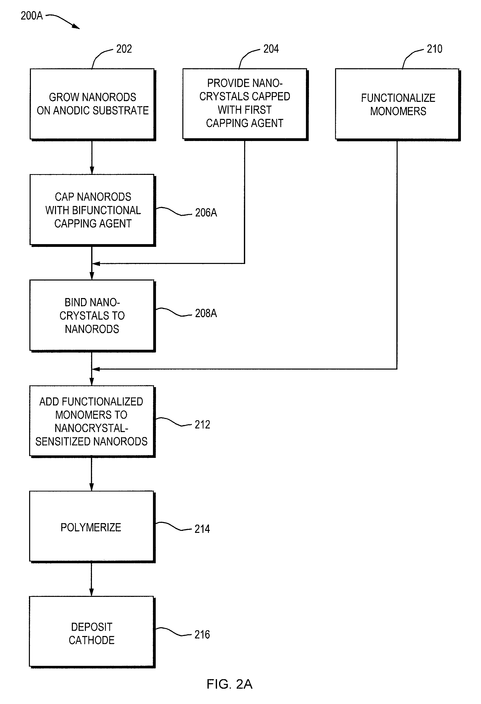
Embodiments of the present invention involve photovoltaic (PV) cells comprising a semiconducting nanorod-nanocrystal-polymer hybrid layer, as well as methods for fabricating the same. In PV cells according to this invention, the nanocrystals may serve both as the light-absorbing material and as the heterojunctions at which excited electron-hole pairs split.

Description

CROSS-REFERENCE TO RELATED APPLICATION[0001]This application claims priority to and the benefits of U.S. Provisional Application Ser. No. 60 / 926,103, filed on Apr. 25, 2007, the entire disclosure of which is hereby incorporated by reference.FIELD OF THE INVENTION[0002]The present invention relates to solar cells and their fabrication, and in particular to nanorod-nanocrystal-polymer hybrid solar cellsBACKGROUND[0003]To create useful electrical current from electromagnetic radiation, photovoltaic (PV) cells must absorb incident radiation such that an electron is promoted from the valence band to the conduction band (leaving a hole in the valence band), and must be able to separate the electron and hole and deliver these charge carriers to their respective electrodes before they recombine.[0004]Many different strategies based on diverse materials have been employed, with varying degrees of success, to realize these basic behaviors with commercially satisfactory efficiency. Representat...

Claims


Application Information

Patent Timeline
Patent Type & Authority Applications(United States)
IPC IPC(8): H01L31/18
CPCH01L51/0006H01L51/0036H01L31/035227H01L51/426Y02E10/549H01L51/422Y02P70/50H10K71/125H10K85/113H10K30/15H10K30/35B82B1/00H10K30/00
Inventor HARRIS, JAMESPICKETT, NIGEL
Owner NANOCO TECH LTD
Learn More