
Delatch device having both push and pull operability for use with an optical transceiver module, and a method

a technology of optical transceiver and latch device, which is applied in the field of latch device, can solve the problems of increasing the difficulty of removing the module in this manner, increasing the difficulty of gripping each module, and requiring significant upward force, so as to facilitate the removal of the optical transceiver module, the effect of substantially rigid structure and sufficient stiffness

Active Publication Date: 2012-02-02
AVAGO TECH INT SALES PTE LTD
View PDF23 Cites 17 Cited by
  • Summary
  • Abstract
  • Description
  • Claims
  • Application Information

AI Technical Summary

Benefits of technology

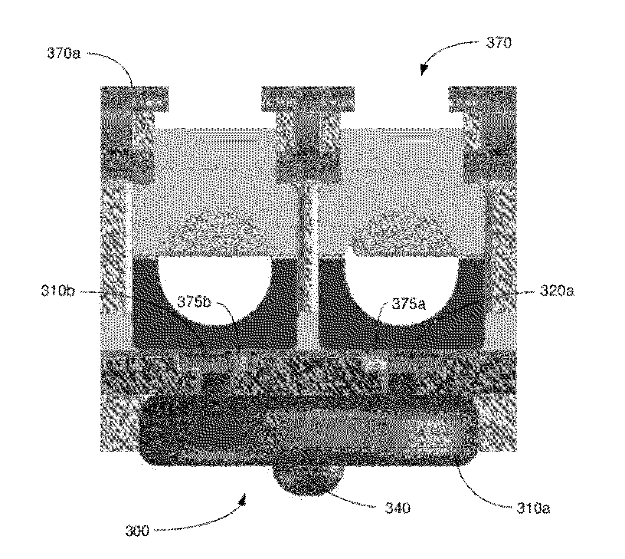
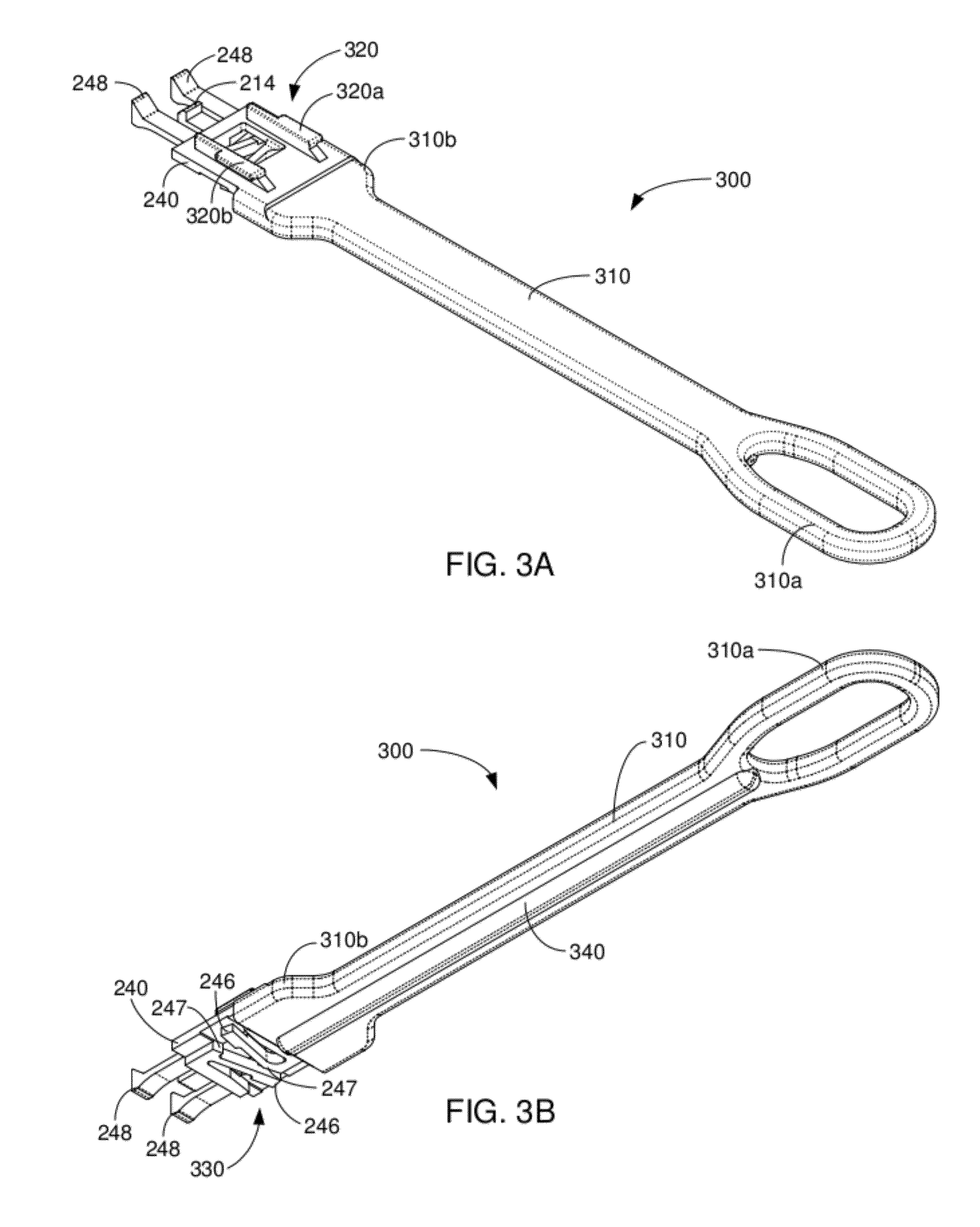
[0014]The invention is directed to a delatch device and method that enables a user to easily push an optical transceiver module into a cage without the user having to have direct manual access to the front face of the module in order to push the module into the cage. The delatch device comprises an elongated handle having a proximal end and a distal end, a module coupling mechanism disposed on an upper surface of the distal end of the handle, and a delatch mechanism disposed on a lower surface of the distal end of the elongated handle. The elongated handle has a substantially rigid structure and is of sufficient stiffness to prevent the elongated handle from buckling or bending if a user uses the proximal end of the handle to push an optical transceiver module coupled to the distal end of the handle into a cage to latch the module within the cage. The module coupling mechanism is configured to mechanically couple an optical transceiver module to the distal end of the elongated handle. The delatch mechanism is configured to latch with a latching feature of a cage in a latched position and to delatch from the latching feature of the cage in a delatched position.
[0015]The method comprises providing a delatch device comprising an elongated handle, positioning the distal end of the elongated handle having the optical transceiver module coupled therewith in an opening of a cage, and applying a force on the proximal end of the elongated handle in a direction substantially toward the cage opening to cause the distal end of the handle having the module coupled therewith to be pushed into the cage opening. The elongated handle has a substantially rigid structure and is of sufficient stiffness to prevent the handle from buckling or bending when the force is applied to the proximal end of the handle to push the module coupled to the distal end of the handle into the cage. When the module has been pushed a particular distance into the cage opening, the delatch mechanism latches with a latching feature of the cage in a latched position.

Problems solved by technology

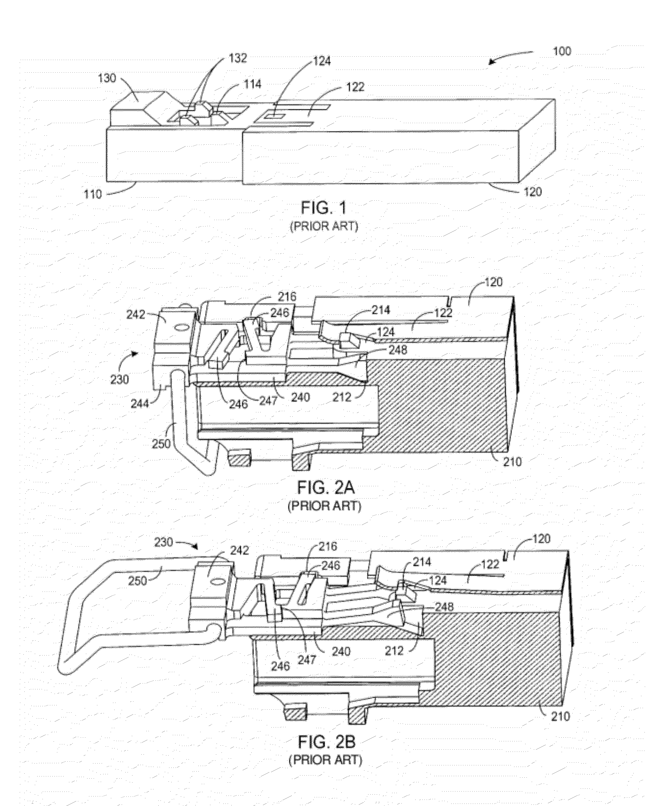
Additionally, when module 110 is in an array of modules in an optical switch, modules above module 110 will often block easy access to delatch mechanism 130, making removal of module 110 more difficult.
Surrounding modules also make each module more difficult to grip.
Releasing the latch tab and removing the module in this manner requires significant upward force.
For many operators, the operation of this delatch mechanism is not intuitive since pulling directly out on the flexible tab will not release the module.
Additionally, in a high-density configuration, surrounding modules can make the flexible tab difficult to grip.
This system requires an operator to apply a great deal of force to remove the module.
In such arrangements, it can be difficult for a user to push with a finger on these features of the module due to the closeness of the modules within the array, which can prevent the user from having the direct manual access to the modules that is needed to push them into the cages.
Also, the bail 250 is too short to be used very effectively for this purpose.

Method used


Image

  • Delatch device having both push and pull operability for use with an optical transceiver module, and a method
  • Delatch device having both push and pull operability for use with an optical transceiver module, and a method
  • Delatch device having both push and pull operability for use with an optical transceiver module, and a method

Examples


Embodiment Construction

[0024]In accordance with the invention, an optical transceiver module is provided with a delatch device that is configured for pushing and pulling an optical transceiver module into and out of a cage. The delatch device includes an elongated handle having at least one strength member integrally formed therein or secured thereto that provides the handle with a sufficient moment of inertia to prevent the handle from bending or buckling when the elongated handle is being used to push an optical transceiver module into a cage. The elongated handle allows a module to easily be inserted into a cage by a user without the user having to directly access the front face of the module. The delatch device will now be described with reference to a few illustrative embodiments in order to demonstrate the principles and concepts of the invention.

[0025]FIGS. 3A-3C illustrate top perspective, bottom perspective and side views, respectively, of the delatch device 300 in accordance with an illustrative...


PUM

PropertyMeasurementUnit
lengthaaaaaaaaaa
stiffnessaaaaaaaaaa
strengthaaaaaaaaaa

Abstract

An optical transceiver module is provided with a delatch device that is configured for pushing and pulling an optical transceiver module into and out of a cage. The delatch device includes an elongated handle having at least one strength member integrally formed therein or secured thereto that provides the handle with a sufficient moment of inertia to prevent the handle from bending or buckling when a force is being applied to the elongated handle to push an optical transceiver module into a cage. The elongated handle allows a module to easily be inserted into a cage by a user without the user having to directly access the front face of the module.

Description

TECHNICAL FIELD OF THE INVENTION[0001]The invention relates to optical transceiver modules. More particularly, the invention relates to a delatch device that has both push and pull latching and delatching operability for use with an optical transceiver module.BACKGROUND OF THE INVENTION[0002]State-of-the-art digital communication switches, servers, and routers currently use multiple rows of duplex LC connector optical transceivers to meet information bandwidth and physical density needs. To be a commercially fungible product, the optical transceivers must have basic dimensions and mechanical functionality that conform to an industry standard Multi-Source Agreement (MSA) such as set forth in the Small Form Factor (SFF) committee's INF-8074i “SFP Transceiver” document. Many optical transceiver mechanical designs that comply with and add value beyond the basic mechanical functionally set forth in the MSA are possible.[0003]FIG. 1 illustrates a standard configuration for a system 100 in...

Claims


Application Information

Patent Timeline
Patent Type & Authority Applications(United States)
IPC IPC(8): G02B6/36B23P19/04
CPCG02B6/4261Y10T29/49947G02B6/4292
Inventor YI, ROBERT
Owner AVAGO TECH INT SALES PTE LTD
Learn More