
Light Guide Plate and Manufacturing Method Thereof

a technology of light guide plate and manufacturing method, which is applied in the field of light guide plate, can solve the problems of difficult control of the uniformity of diffuser particles filled into the light guide plate, difficulty in achieving the expected diffuser effect, and the foregoing method has encountered practically some problems, so as to reduce the thickness and weight and simplify the components of the backlight module

Active Publication Date: 2012-02-02
SHENZHEN CHINA STAR OPTOELECTRONICS TECH CO LTD
View PDF3 Cites 10 Cited by
  • Summary
  • Abstract
  • Description
  • Claims
  • Application Information

AI Technical Summary

Benefits of technology

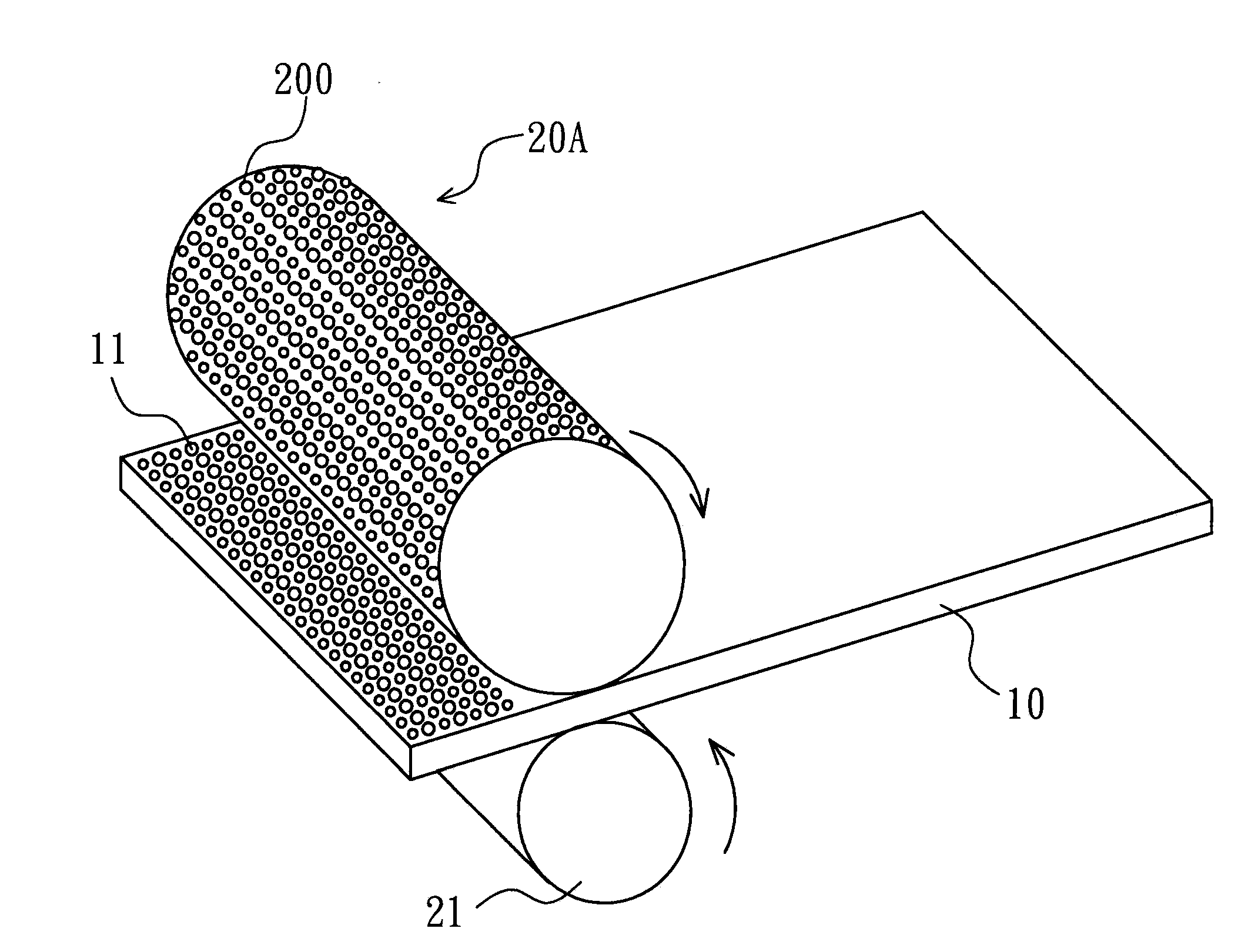
[0010]A primary object of the invention is to provide a manufacturing method of light guide plate which is firstly formed with a plurality of spherical recesses on a light guide plate body, and then correspondingly applied with a plurality of diffuser particles on the spherical recesses to form the light guide plate. The method effectively increases matte degree of the light guide plate that reaches matte degree of a traditional diffuser film, helps to simplify components of a backlight module and reduces the thickness and weight of the backlight module.
[0011]A secondary object of the present invention is to provide a light guide plate which is made by the foregoing manufacturing method and provides a matte degree reached by a traditional light guide plate with a diffuser film as well, so as to benefit simplification of components of a backlight module.
[0024]Comparing with the existing techniques, the manufacturing method of the light guide plate effectively increases matte degree of the light guide plate, so as to not only reduces the use of diffuser films, but also effectively reduces thickness and weight of the backlight module while processing manufacturing of a backlight module.

Problems solved by technology

However, foregoing method has practically encountered some problems during the manufacturing process.
The light guide plate made by the third method difficulty achieve an expected diffuser effect since the uniformity of the diffuser particles filled into the light guide plate is difficult to control.

Method used


Image

  • Light Guide Plate and Manufacturing Method Thereof
  • Light Guide Plate and Manufacturing Method Thereof
  • Light Guide Plate and Manufacturing Method Thereof

Examples


Embodiment Construction

[0031]The foregoing objects, features and advantages adopted by the present invention can be best understood by referring to the following detailed description of the preferred embodiments and the accompanying drawings.

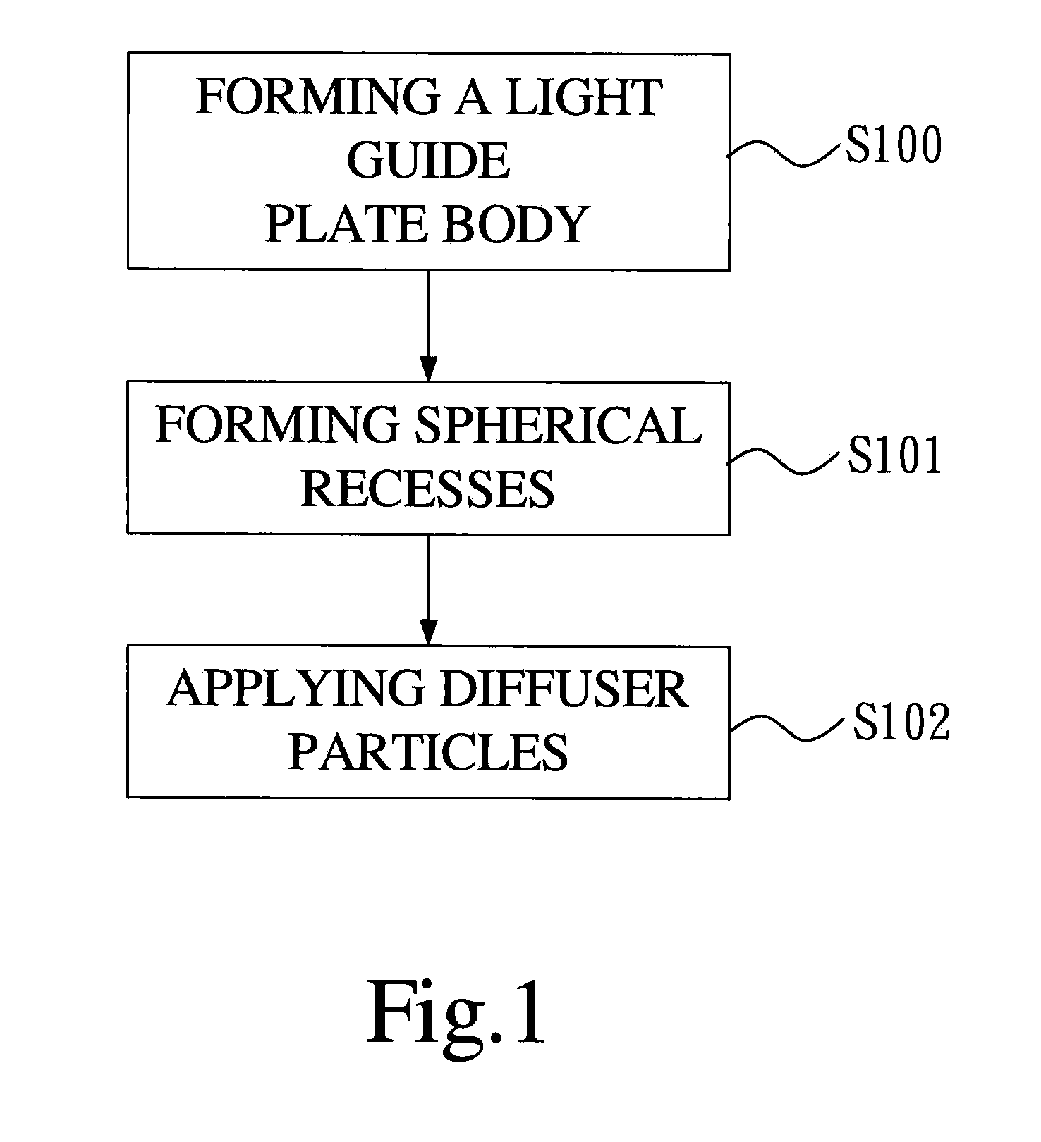
[0032]With reference to FIG. 1, FIG. 1 discloses a manufacturing method of a light guide plate according to a preferred embodiment of the present invention. The manufacturing method comprises a step S100 of forming a light guide plate body, a step S101 of forming spherical recesses and a step S102 of applying diffuser particles.

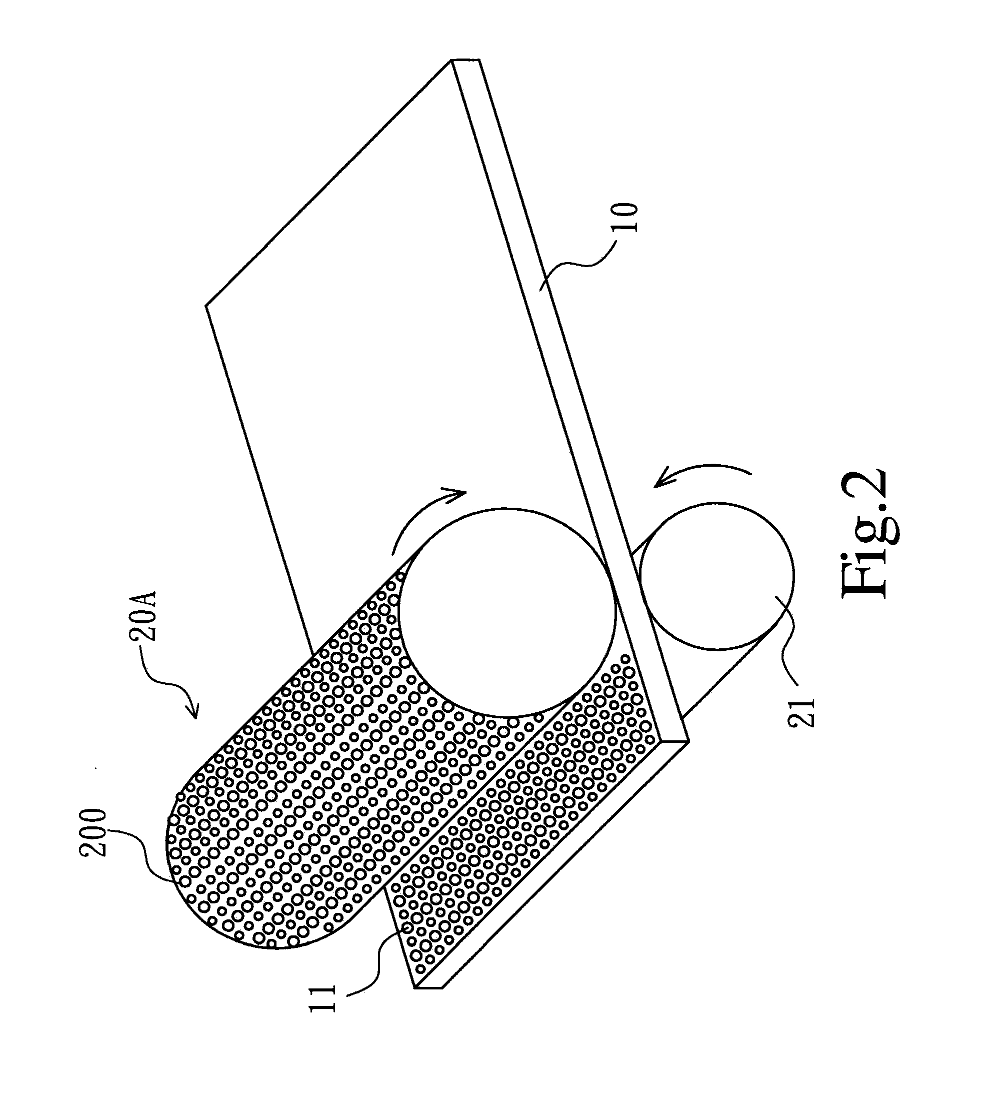
[0033]Also referring to FIG. 2, FIG. 2 discloses an operational view of the step S101 of forming spherical recesses according to a first embodiment of the present invention. The step S100 of forming a light guide plate body is using a means of pressing to form a light guide plate body 10. The material of the light guide plate body 10 may be selected from thermoplastics, such as poly(methyl methacrylate) (PMMA), polycarbonate (PC), and etc.

[0034...


PUM


Abstract

The present invention provides a light guide plate and a manufacturing method thereof. The manufacturing method firstly forms a plurality of spherical recesses arranged at intervals on a light-emitting surface of a light guide plate body when the light guide plate body is formed by pressing, and then applies a diffuser particle with corresponding shape on a surface of each of the spherical recesses, so as to complete the manufacture of the light guide plate. When being mounted in a backlight module, the light guide plate benefits the backlight module of reducing the use of diffuser films, so as to reduce the thickness and weight of the backlight module.

Description

FIELD OF THE INVENTION[0001]The present invention relates to a light guide plate and a manufacturing method thereof, and more particularly to a light guide plate and a manufacturing method thereof that reduces the use of diffuser films in a backlight module when assembling the backlight module.BACKGROUND OF THE INVENTION[0002]A light guide plate belongs to assembling members of a backlight module and plays an important role therein. At present, a light-emitting surface of the light guide plate used in the backlight module is mainly a smooth flat structure. Therefore, the light guide plate only provides a light-guiding function, the light guiding process thereof is run by the dot reflection structures arranged on a bottom of the light guide plate that are corresponding to lights emitted into the light guide plate; after being reflected, the lights will emit out of the light-emitting surface of the light guide plate that is parallel to the arrangement surface of the dot reflection str...

Claims


Application Information

Patent Timeline
IPC IPC(8): F21V8/00B05D5/06
CPCG02B6/0043G02B6/0065G02B6/0051
Inventor FANG, LINDONGKUO, YICHENG
Owner SHENZHEN CHINA STAR OPTOELECTRONICS TECH CO LTD
Learn More