
Zoom lens

a zoom lens and zoom technology, applied in the field of zoom lenses, can solve the problems of insufficient luminous flux, insufficient stop application, inability to achieve high resolution advantages, etc., and achieve the effect of effectively eliminating image aberration

Active Publication Date: 2012-02-02
YOUNG OPTICS
View PDF0 Cites 22 Cited by
  • Summary
  • Abstract
  • Description
  • Claims
  • Application Information

AI Technical Summary

Benefits of technology

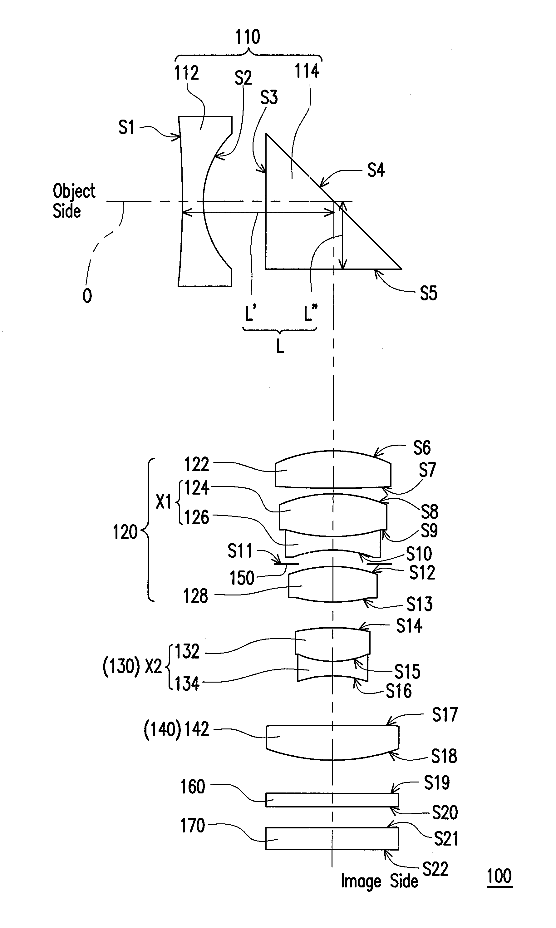
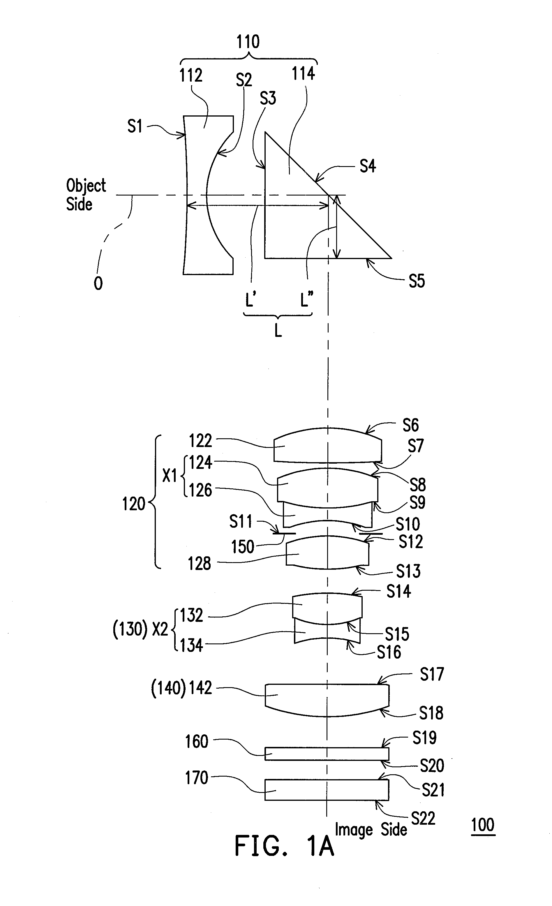
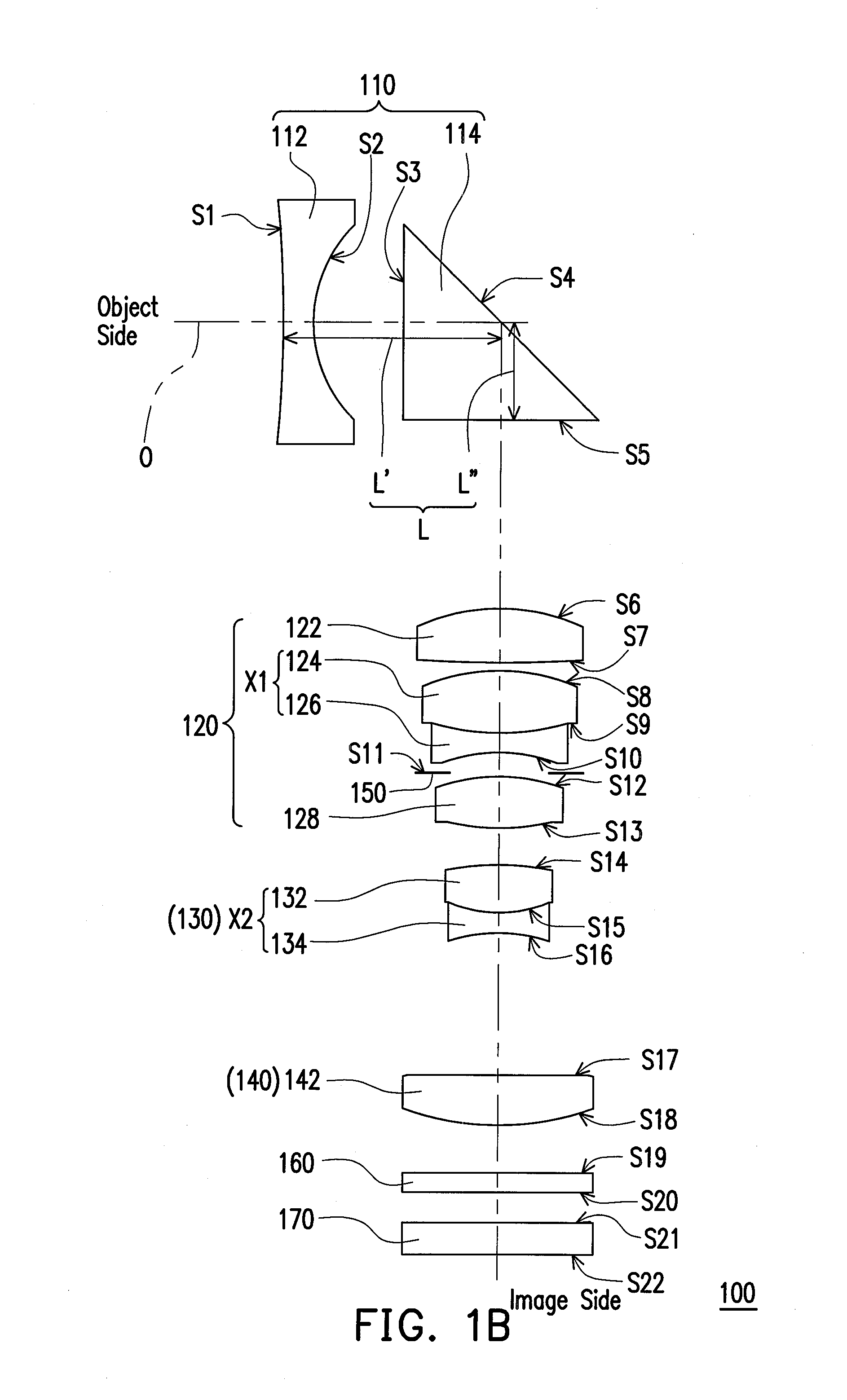
The invention is a zoom lens with a small size and effective zoom function. It includes a negative, positive, negative, and positive combination of refractive powers to eliminate image aberration. The lens includes aspheric lenses, double cemented lenses, and prisms to achieve miniaturization. The technical effects of the invention include improved image quality and reduced size of the zoom lens.

Problems solved by technology

However, in current zoom lens designs, due to more manufacturing difficulties and limited by stricter tolerances, these designs cannot concurrently achieve advantages of high resolution, large stops, and wide angle of view.
Moreover, insufficient luminous flux, noise accumulation, and underexposure typically results when small stops are applied in digital video cameras used during nighttime.
For example, U.S. Pat. Nos. 7,242,529 and 7,110,186 disclose stops having F-numbers above 3.5, which may easily result in insufficient luminous flux.
Moreover, in the zoom lens disclosed by U.S. Pat. No. 7,242,529, not only does the disclosed zoom lens not meet the need of large stops, but a field of view is only 31.9 degrees, resulting in a reduced shooting range and insufficient luminous flux.
On the other hand, although the zoom lens disclosed by U.S. Pat. No. 7,177,100 has advantages such as a 3× zoom capability, a wide angle of view, and large stops, the zoom function cannot be accomplished within the lens body, and therefore the lens module cannot be miniaturized.

Method used


Image

  • Zoom lens
  • Zoom lens
  • Zoom lens

Examples


Embodiment Construction

[0020]In the following detailed description of the preferred embodiments, reference is made to the accompanying drawings which form a part hereof, and in which are shown by way of illustration specific embodiments in which the invention may be practiced. In this regard, directional terminology, such as “top,”“bottom,”“front,”“back,” etc., is used with reference to the orientation of the Figure(s) being described. The components of the invention can be positioned in a number of different orientations. As such, the directional terminology is used for purposes of illustration and is in no way limiting. On the other hand, the drawings are only schematic and the sizes of components may be exaggerated for clarity. It is to be understood that other embodiments may be utilized and structural changes may be made without departing from the scope of the invention. Also, it is to be understood that the phraseology and terminology used herein are for the purpose of description and should not be ...


PUM


Abstract

A zoom lens disposed between an object side and an image side and including a first, second, third, and fourth lens group is provided. The first lens group has a negative refractive power and includes a first lens and a prism arranged in sequence from the object side to the image side. The first lens is an aspheric lens. A distance between the first lens and the prism is L, an effective focal length of the zoom lens at a wide-end is fw, and 1.58<L / fw<1.88. The second lens group disposed between the first lens group and the image side has a positive power and includes a first double cemented lens. The third lens group disposed between the second lens group and the image side has a negative power and includes a second double cemented lens. The fourth lens group has a positive power.

Description

CROSS-REFERENCE TO RELATED APPLICATION[0001]This application claims the priority benefit of Taiwan application serial no. 99125124, filed on Jul. 29, 2010. The entirety of the above-mentioned patent application is hereby incorporated by reference herein and made a part of this specification.BACKGROUND OF THE DISCLOSURE[0002]1. Field of Invention[0003]The invention generally relates to a lens, and more particularly, to a zoom lens.[0004]2. Description of Related Art[0005]As state of the art videoconferencing technologies advance, the need for a high pixel and high quality digital video camera (DVC) and digital camera (DC) has been gradually rising, while trending towards miniaturization, large stops, and wide view angle. In order to achieve large stops and wide view angle within a small space, a significant emphasis is placed on the lens design framework.[0006]However, in current zoom lens designs, due to more manufacturing difficulties and limited by stricter tolerances, these desig...

Claims


Application Information

Patent Timeline
Patent Type & Authority Applications(United States)
IPC IPC(8): G02B15/14
CPCG02B13/0065G02B15/177G02B13/009G02B15/144511
Inventor WANG, KUO-CHUANCHEN, HSIN-TE
Owner YOUNG OPTICS
Learn More