
High temperature capacitive static/dynamic pressure sensors and methods of making the same

a capacitive static/dynamic pressure sensor, high temperature technology, applied in the direction of variable capacitors, fluid pressure measurement, instruments, etc., can solve the problems of difficult to develop high temperature capacitive pressure sensors for harsh environment applications, limited applicability of devices at elevated temperatures, and stray capacitance and other environmental conditions, so as to reduce the temperature required for fusion

Active Publication Date: 2012-02-02
ROSEMOUNT AEROSPACE
View PDF0 Cites 19 Cited by
  • Summary
  • Abstract
  • Description
  • Claims
  • Application Information

AI Technical Summary

Benefits of technology

[0013]A sapphire substrate is disposed within the interior sensing chamber of the housing. The periphery of the sapphire substrate is fused to the sapphire diaphragm to form a sapphire stack and a reference chamber is defined between the central portion of the sapphire diaphragm and a central portion of sapphire substrate. The sapphire substrate has a second electrode formed on its central portion opposite the first electrode. Prior to fusing the sapphire diaphragm to the sapphire substrate, all contact surfaces are chemically treated (e.g. RCA cleaned) and prepared using plasma activation, so as to create a bonding layer and to reduce the temperature required for the fusion.
[0031]Preferably, prior to fusing the sapphire diaphragm to the sapphire substrate, all contact surfaces are chemically treated (e.g. RCA cleaned) and prepared using plasma activation, so as to create a bonding layer and to reduce the temperature required for the fusion.

Problems solved by technology

Traditionally, these devices have had limited applicability at elevated temperatures.
In particular, since the capacitance of prior art pressure sensors are normally in the picoFarad (pF) range, they are susceptible to stray capacitance and other environmental conditions.
This makes it difficult to develop high temperature capacitive pressure sensors for use in harsh environment applications, such as, gas turbine applications.
Indeed, there are currently no commercially available capacitive pressure sensors capable of operating above 350° C.
This makes the direct current (DC) signal difficult to detect at high temperatures.
However, one of the drawbacks of a metal diaphragm in a pressure sensor or microphone is temperature hysteresis and pressure hysteresis at high temperature.
Usually, sensor failure at high temperature is due to the degrading of the electrical connection between the contacts and the output leads.
Second, the thermal mismatch between Pyrex and silicon degrades the sensor accuracy at high temperature range.
It is known that piezoresistive pressure sensors are temperature sensitive which requires complicated temperature compensation.

Method used


Image

  • High temperature capacitive static/dynamic pressure sensors and methods of making the same
  • High temperature capacitive static/dynamic pressure sensors and methods of making the same
  • High temperature capacitive static/dynamic pressure sensors and methods of making the same

Examples


Embodiment Construction

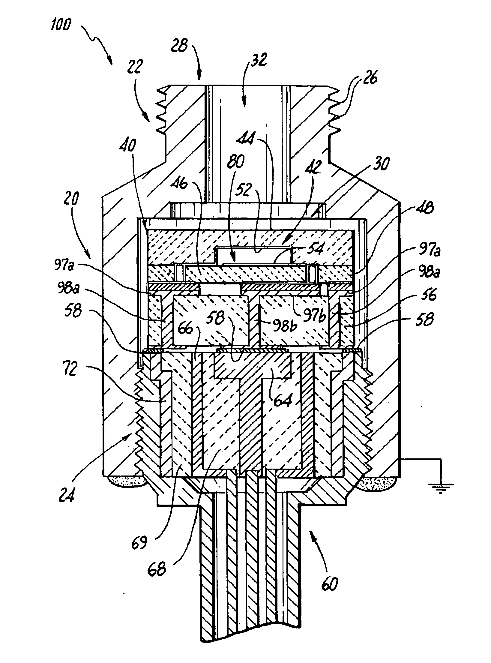
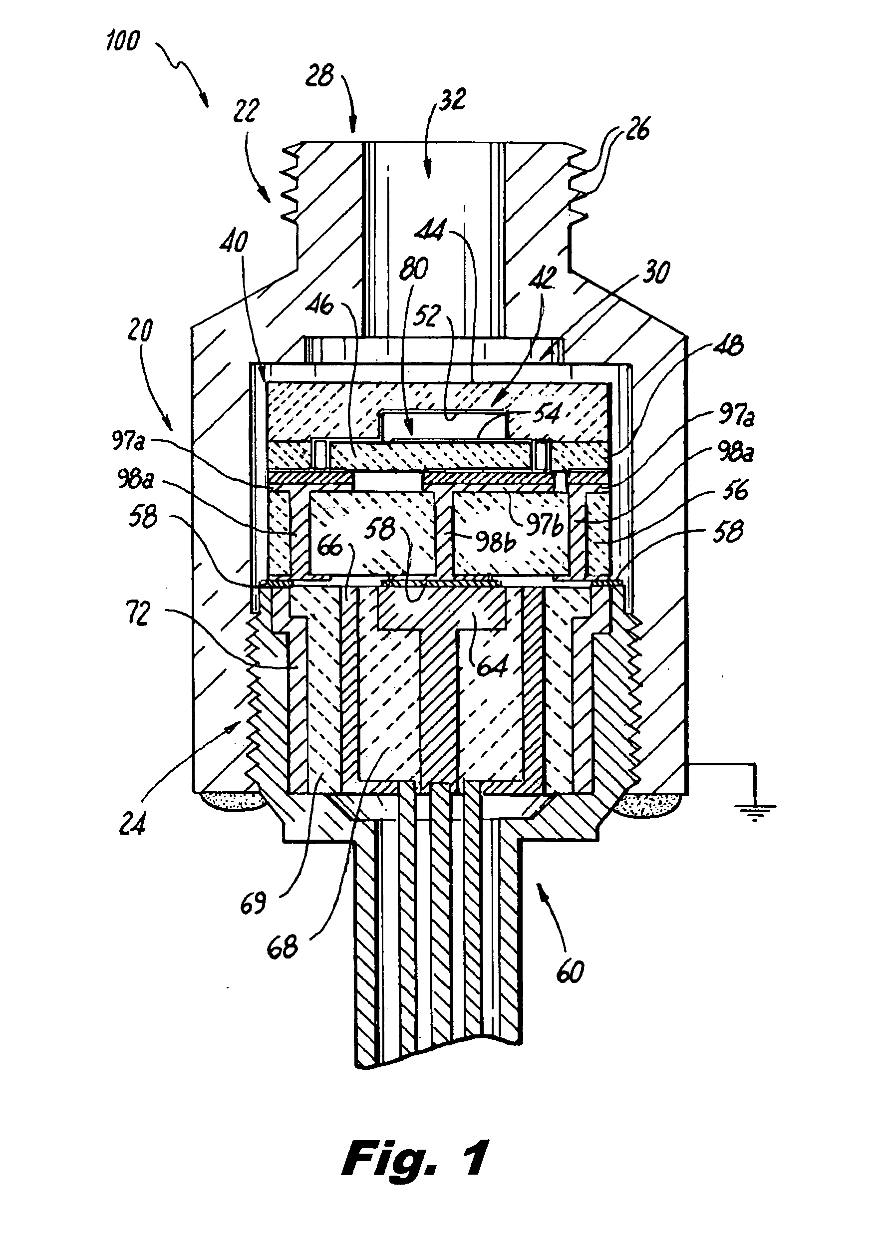
[0047]Referring now to the drawings wherein similar reference numerals identify similar structural features or aspects of the capacitive sensors of the subject invention, there is illustrated in FIG. 1, a capacitive probe or pressure sensor constructed in accordance with a preferred embodiment of the subject invention and designated generally by reference numeral 100. Pressure sensor 100 is adapted and configured for high temperature applications, such as for use in a gas turbine engine.

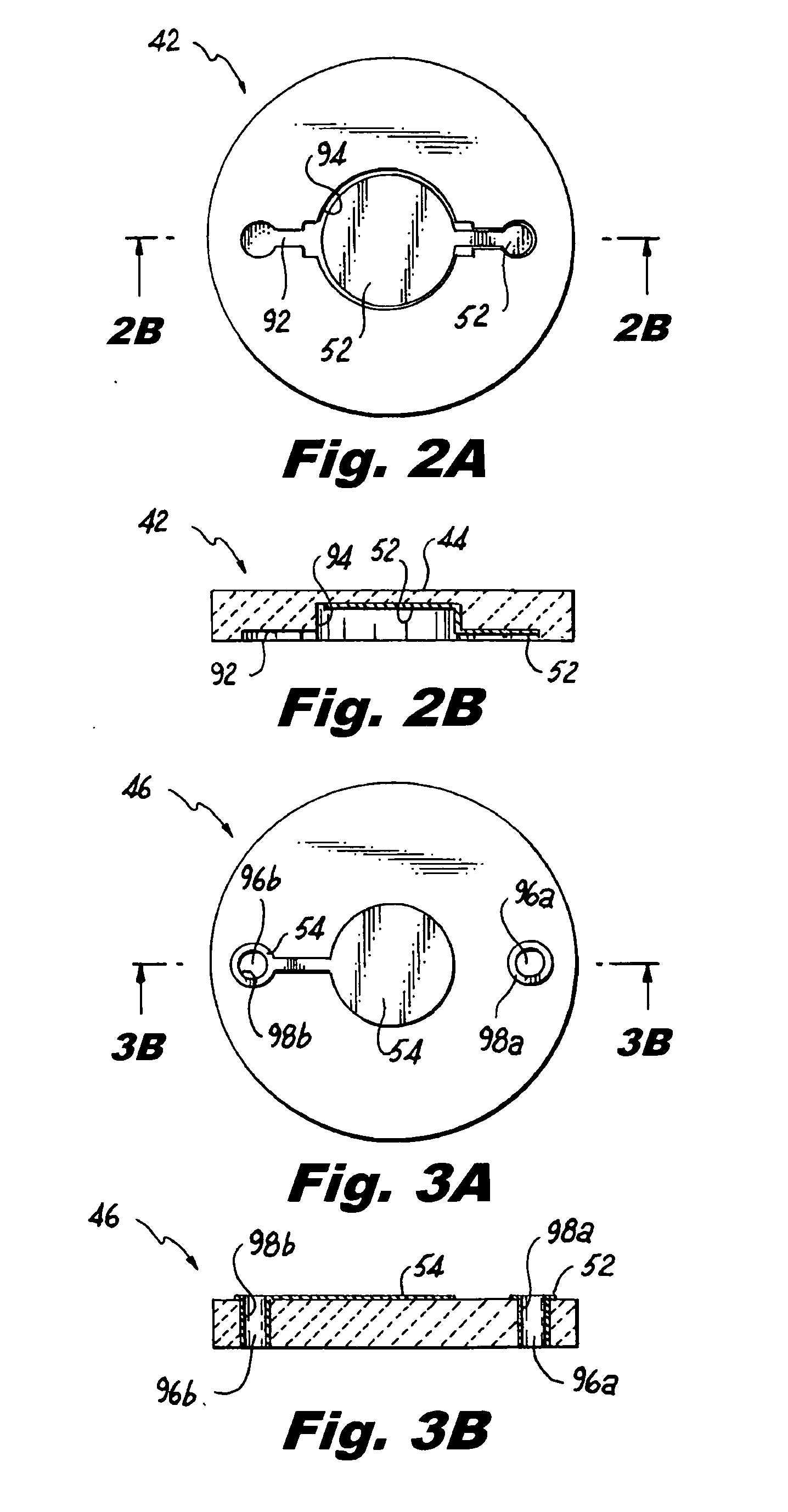
[0048]Referring to FIGS. 1 through 7, pressure sensor 100 includes a housing assembly 20 having a mounting section 22 and electrode support section 24. The electrode support section 24 is adapted and configured for receiving an electrode assembly 60 which will be discussed hereinbelow.

[0049]The mounting section 22 of the housing assembly 20 includes a series of threads 26 associated with end 28. The threads 26 can be used to connect the sensor 100 to the pressure source to be measured. For example, t...


PUM

PropertyMeasurementUnit
Temperatureaaaaaaaaaa
Electrical conductoraaaaaaaaaa
Electric potential / voltageaaaaaaaaaa

Abstract

Disclosed are capacitive pressure probes or sensors for high temperature applications. The capacitive pressure sensors of the present invention include, inter alia, a sapphire diaphragm which is disposed within an interior sensing chamber of the probe housing and has a first electrode formed on a central portion thereof. The central portion of the diaphragm and the first electrode are adapted and configured to deflect in response to pressure variations encountered within an interior sensing chamber and by the pressure sensor. A sapphire substrate which has a second electrode formed thereon is fused to the sapphire diaphragm about its periphery to form a sapphire stack and to define a reference chamber therebetween. Prior to fusing the sapphire diaphragm to the sapphire substrate, all contact surfaces are chemically treated and prepared using plasma activation, so as to create a bonding layer and to reduce the temperature required for the fusion.

Description

BACKGROUND OF THE INVENTION[0001]1. Field of the Invention[0002]The subject invention is directed to capacitive pressure sensors, and more particularly, to high temperature capacitive static / dynamic pressure sensors, such as sensors or microphones for detecting acoustic pressure waves in a gas turbine engine, which employs a diaphragm made from a material exhibiting high thermal strength, thermal stability and oxidation resistance at elevated temperatures.[0003]2. Description of Related Art[0004]Capacitive pressure sensors are well known in the art, as disclosed for example in U.S. Pat. No. 6,148,674, the disclosure of which is herein incorporated by reference in its entirety. Traditionally, these devices have had limited applicability at elevated temperatures. In particular, since the capacitance of prior art pressure sensors are normally in the picoFarad (pF) range, they are susceptible to stray capacitance and other environmental conditions. This makes it difficult to develop hig...

Claims


Application Information

Patent Timeline
IPC IPC(8): G01L9/12H05K13/00
CPCG01L9/0075Y10T29/49002G01L19/04
Inventor GUO, SHUWEN
Owner ROSEMOUNT AEROSPACE
Learn More