
Inflation media for implants

a technology of inflation media and implants, applied in the field of medical methods and devices, can solve the problems of inability to carry on any physical activity without discomfort, limited physical activity, and marked limitation of physical activity

Inactive Publication Date: 2012-01-26
SPEYSIDE MEDICAL LLC
View PDF6 Cites 116 Cited by
  • Summary
  • Abstract
  • Description
  • Claims
  • Application Information

AI Technical Summary

Benefits of technology

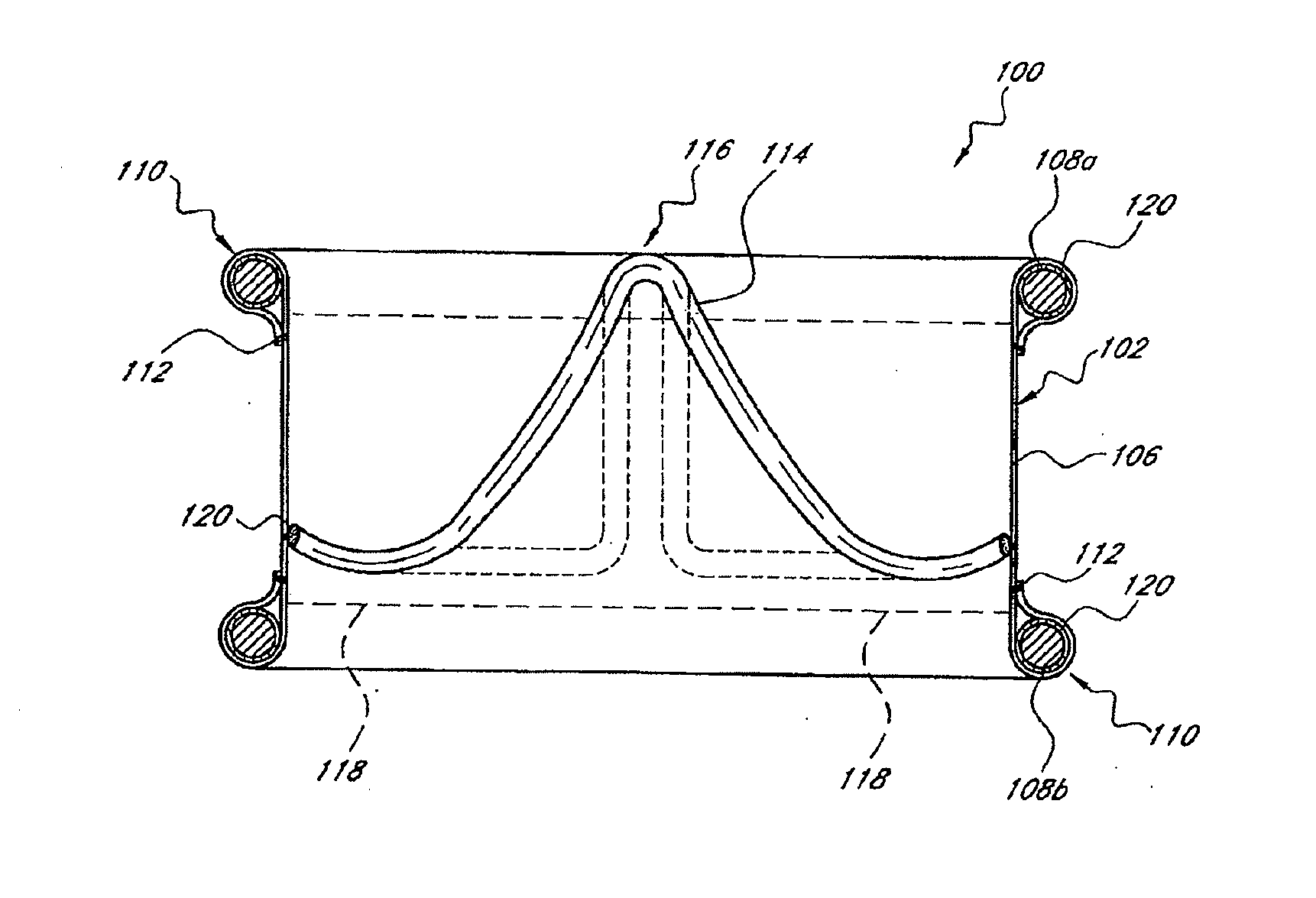
[0022]One embodiment provides an inflatable implant comprises at least one inflation channel for forming an inflatable structure of the inflatable implant; and an inflation media disposed within the at least one inflation channel, wherein the inflation media comprises a mixture of an epoxy resin and a hardener, the mixture is configured to have an average viscosity of less than about 100 cps at about 37° C. over the first 10 minutes after mixing, and gel at about 37° C. in less than about 2.5 hours after mixing to form a gelled mixture.

Problems solved by technology

Patient with cardiac disease resulting in slight limitation of physical activity.
Patients with cardiac disease resulting in marked limitation of physical activity.
Patients with cardiac disease resulting in inability to carry on any physical activity without discomfort.
If any physical activity is undertaken, discomfort is increased.
Access to these sites generally include a thoracotomy or a sternotomy for the patient and include a great deal of recovery time.
Although valve repair and replacement can successfully treat many patients with valvular insufficiency, techniques currently in use are attended by significant morbidity and mortality.
Despite the many years of effort, and enormous investment of entrepreneurial talent and money, no stent based heart valve system has yet received regulatory approval, and a variety of difficulties remain.
For example, stent based systems have a fixed rigidity even in the collapsed configuration, and have inherent difficulties relating to partial deployment, temporary deployment, removal and navigation.

Method used


Image

  • Inflation media for implants
  • Inflation media for implants
  • Inflation media for implants

Examples


Embodiment Construction

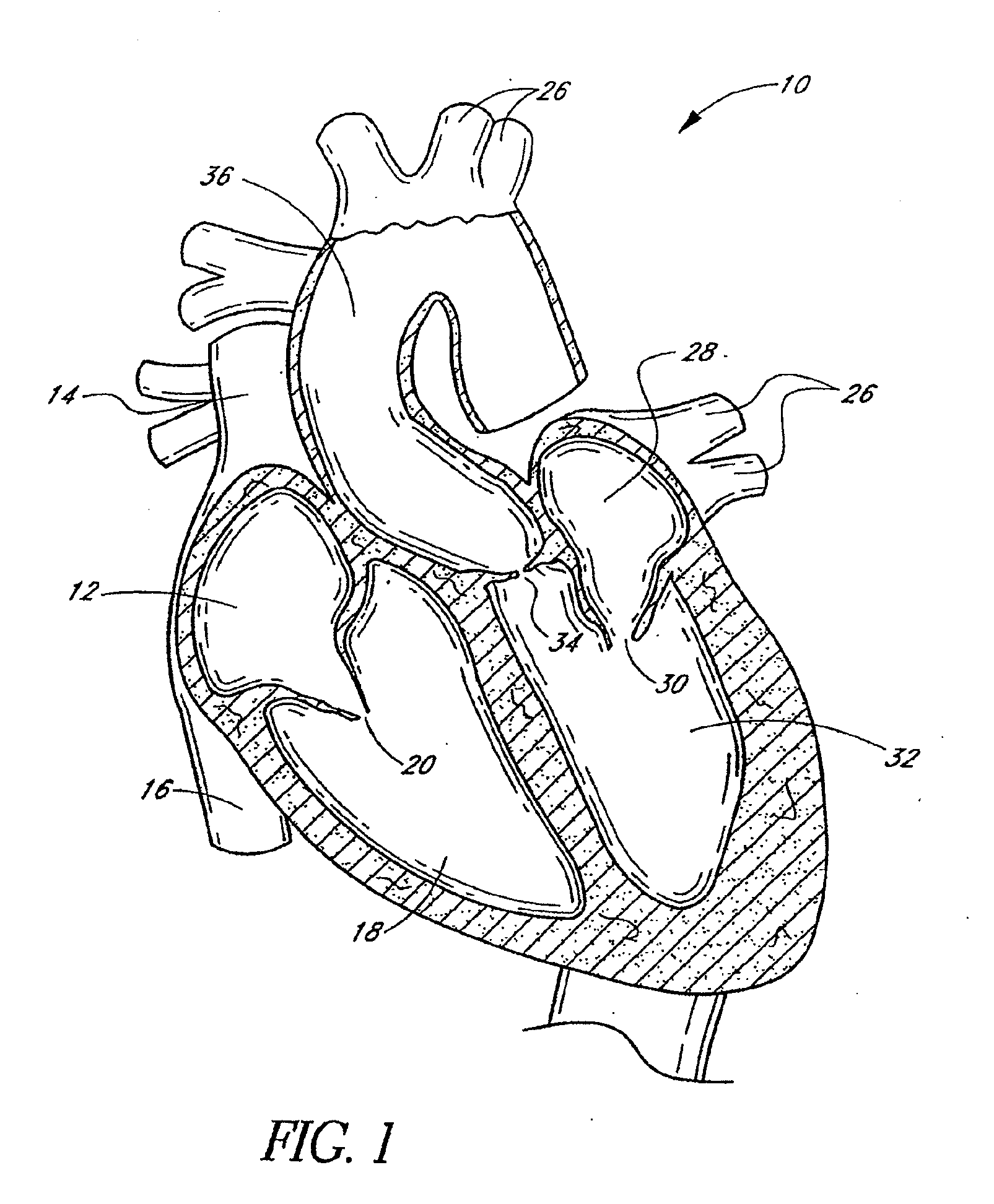
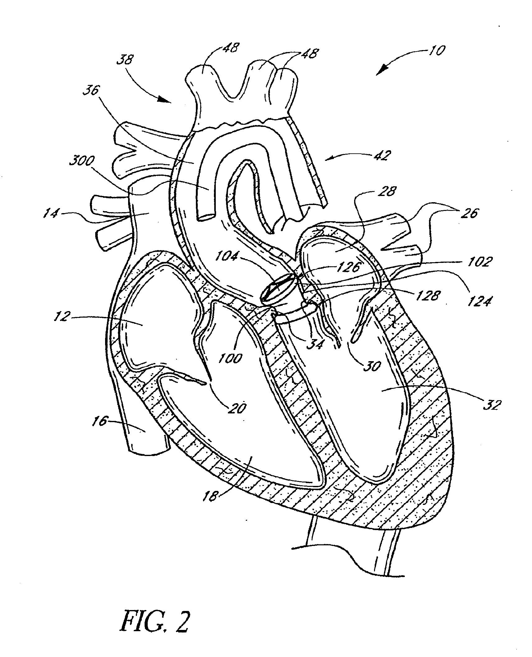
[0047]FIG. 1 is a schematic cross-sectional illustration of the anatomical structure and major blood vessels of a heart 10. Deoxygenated blood is delivered to the right atrium 12 of the heart 10 by the superior and inferior vena cava 14, 16. Blood in the right atrium 12 is allowed into the right ventricle 18 through the tricuspid valve 20. Once in the right ventricle 18, the heart 10 delivers this blood through the pulmonary valve 22 to the pulmonary arteries 24 and to the lungs for a gaseous exchange of oxygen. The circulatory pressures carry this blood back to the heart via the pulmonary veins 26 and into the left atrium 28. Filling of the left atrium 28 occurs as the mitral valve 30 opens allowing blood to be drawn into the left ventricle 32 for expulsion through the aortic valve 34 and on to the body extremities through the aorta 36. When the heart 10 fails to continuously produce normal flow and pressures, a disease commonly referred to as heart failure occurs.

[0048]One cause o...


PUM

PropertyMeasurementUnit
tensile strengthaaaaaaaaaa
temperatureaaaaaaaaaa
tensile strengthaaaaaaaaaa

Abstract

An inflatable implant is disclosed. The inflatable implant comprises at least one inflation channel for forming an inflatable structure of the inflatable implant; and an inflation media disposed within the at least one inflation channel, wherein the inflation media comprises a mixture of an epoxy resin and a hardener, the mixture is configured to gel at about 37° C. in less than about 2.5 hours after mixing to form a gelled mixture.

Description

CROSS-REFERENCE TO RELATED APPLICATIONS[0001]This application claims the priority benefit to U.S. Provisional No. 61 / 346,419 filed May 19, 2010, the entirety of which is hereby incorporated by reference herein.BACKGROUND OF THE INVENTION[0002]1. Field of the Invention[0003]The present invention related to medical methods and devices, and, in particular, to an inflation media formulation and the method for using the same for inflatable medical devices, such as percutaneous implants having a formed in place support structure.[0004]2. Description of the Related Art[0005]According to recent estimates, more than 79,000 patients are diagnosed with aortic and mitral valve disease in U.S. hospitals each year. More than 49,000 mitral valve or aortic valve replacement procedures are performed annually in the U.S., along with a significant number of heart valve repair procedures.[0006]The circulatory system is a closed loop bed of arterial and venous vessels supplying oxygen and nutrients to t...

Claims


Application Information

Patent Timeline
Patent Type & Authority Applications(United States)
IPC IPC(8): A61F2/06B29C48/11
CPCA61F2/2418A61F2220/0016A61F2/2439A61F2210/0085A61F2250/0003A61M25/0009A61M25/0023A61M25/005A61M25/0054A61M2025/0046A61M2025/0681B29C47/0028B29L2031/7542C08G59/5026C08L63/00G01N2203/0071G01N2203/0073A61F2220/0008A61F2/2436A61L27/18A61L27/50B29C48/11A61F2310/00005A61F2/24A61B2017/00243A61F2/2427A61F2/2433
Inventor PERERA, ARUNAGREENAN, TREVORROGERS, LARRY
Owner SPEYSIDE MEDICAL LLC
Learn More