
Display device

a display device and display technology, applied in the field of display devices, can solve the problems of difficult to increase the contrast ratio and difficult to apply a large shear stress to the material, and achieve the effect of improving the alignment property of the polarizing layer and increasing the contrast ratio

Inactive Publication Date: 2012-01-26
PANASONIC LIQUID CRYSTAL DISPLAY CO LTD +1
View PDF6 Cites 4 Cited by
  • Summary
  • Abstract
  • Description
  • Claims
  • Application Information

AI Technical Summary

Benefits of technology

[0008]The present invention has been accomplished in view of the foregoings and intends to provide a display device capable of increasing the contrast ratio.
[0018]Accordingly, an acid-base interaction is caused between the acidic group for the dye molecule and the basic group which is the surface functional group for the underlayer film to strengthen a force of fixing the dye molecule having the lyotropic liquid crystallinity to the surface of the underlayer film.
[0019]Therefore, since a large shear stress can be applied to the material, the dye alignment property of the polarizing layer is improved and, as a result, the contrast ratio can be increased.

Problems solved by technology

However, in the display device using the polarizing device as described in JP-A-2007-240906, since the material is separated from the substrate when a large shear stress is applied to the material upon coating the material containing the dye having the lyotropic liquid crystallinity on the substrate, it is difficult to apply a large shear stress to the material and, as a result, it was difficult to increase the contrast ratio.

Method used


Image

  • Display device
  • Display device
  • Display device

Examples


Embodiment Construction

[0029]An embodiment of a display device according to the invention is to be described in details with reference to the drawings.

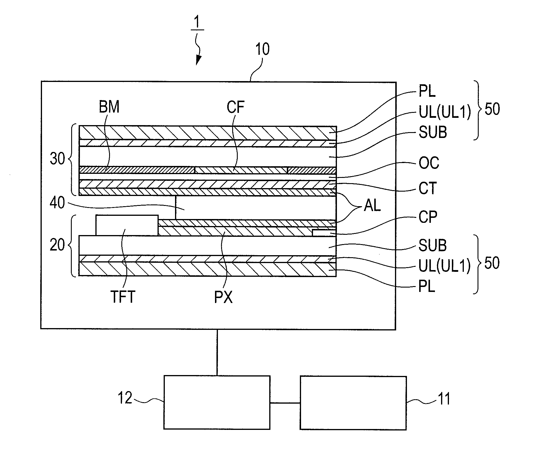
[0030]FIG. 1 is a schematic diagram showing a configuration of a liquid crystal display device 1 according to an embodiment of the invention. The liquid crystal display device 1 is an active matrix driving type liquid crystal display device and has a liquid crystal panel 10, a backlight 11, and a control section 12 as shown in FIG. 1. In FIG. 1, the liquid crystal panel 10 is shown as a cross section for a main portion.

[0031]The liquid crystal display panel 10 has a TFT substrate 20, a color filter substrate 30, and a liquid crystal material 40 put therebetween.

[0032]The TFT substrate 20 has a glass substrate SUB, a thin film transistor TFT, a pixel electrode PX, an accumulation capacitor CP, and an alignment film AL.

[0033]The glass substrate SUB is a transparent substrate made of a glass material. The thin film transistor TFT is a switching device for driv...


PUM

PropertyMeasurementUnit
light transmittanceaaaaaaaaaa
Pkaaaaaaaaaaa
temperatureaaaaaaaaaa

Abstract

A display device capable of improving the contrast ratio and having a polarizing layer formed by applying shear stress to a material containing a dye having a lyotropic liquid crystallinity to align the molecule of the dye, wherein the display device has an underlayer film forming a base for the polarizing layer, the molecule of the dye has a sulfo group, and the underlayer film comprises a material having a basic surface functional group.

Description

CLAIM OF PRIORITY[0001]The present application claims priority from Japanese Patent Application JP 2010-163572 filed on Jul. 21, 2010, the content of which is hereby incorporated by reference into this application.BACKGROUND OF THE INVENTION[0002]1. Field of the Invention[0003]The present invention relates to a display device having a polarizing layer in which a dye molecule is aligned by applying a shear stress to a material containing a dye having lyotropic liquid crystallinity.[0004]2. Description of the Related Art[0005]A polarizing device having a polarizing layer in which dye molecules are aligned by applying shear stress to a material containing a dye having lyotropic liquid crystallinity has been proposed (for example, refer to JP-A-2007-240906). The lyotropic liquid crystallinity means that a material shows a property similar to that of liquid crystal in a state of solution dissolved in a solvent. The dye having the lyotropic liquid crystallinity is soluble, for example, to...

Claims


Application Information

Patent Timeline
Patent Type & Authority Applications(United States)
IPC IPC(8): C09K19/04C09K19/34C09K19/32G02F1/13C09K19/12
CPCC09K19/60Y10T428/1041C09K19/606G02F1/133528C09K2323/031
Inventor HIRATSUKA, TAKATOADACHI, MASAYAITOU, OSAMU
Owner PANASONIC LIQUID CRYSTAL DISPLAY CO LTD
Learn More