Spray gun handle support and quick release trigger assembly

a trigger assembly and handle support technology, applied in the direction of spraying apparatus, liquid spraying apparatus, etc., can solve the problems of not providing quick and easy installation, blankenheim does not relieve the thrust force pushing back against the wrist of the user, and the pressure on the wrist and hand is still high, so as to relieve the stress and strain on the wrist and hand of the user, and high pressure

Inactive Publication Date: 2012-01-19
CROSSLEY III L T TOM
View PDF2 Cites 14 Cited by
  • Summary
  • Abstract
  • Description
  • Claims
  • Application Information

AI Technical Summary

Benefits of technology

[0006]It is an object of this invention to provide an high pressure spray gun handle which relieves the stress and strain on a user's wrist and hand.
[0007]It is an object of this invention to provide an high pressure spray gun handle which can be quickly, easily and removably installed on a conventional high pressure spray gun.
[0008]It is an object of this invention to provide an high pressure spray gun handle which is simple and easy to use.
[0009]It is an object of this in

Problems solved by technology

Barbato requires permanent modification to the conventional handle and therefore does not provide for quick and easy installation.
Further, Barbato hook and loop wrist support allows for limited flexing of a user's wrist but the user's wrist still must maintain angular control of the spray wand and therefore, the wrist and hand

Method used


Image

  • Spray gun handle support and quick release trigger assembly
  • Spray gun handle support and quick release trigger assembly
  • Spray gun handle support and quick release trigger assembly

Examples


Embodiment Construction

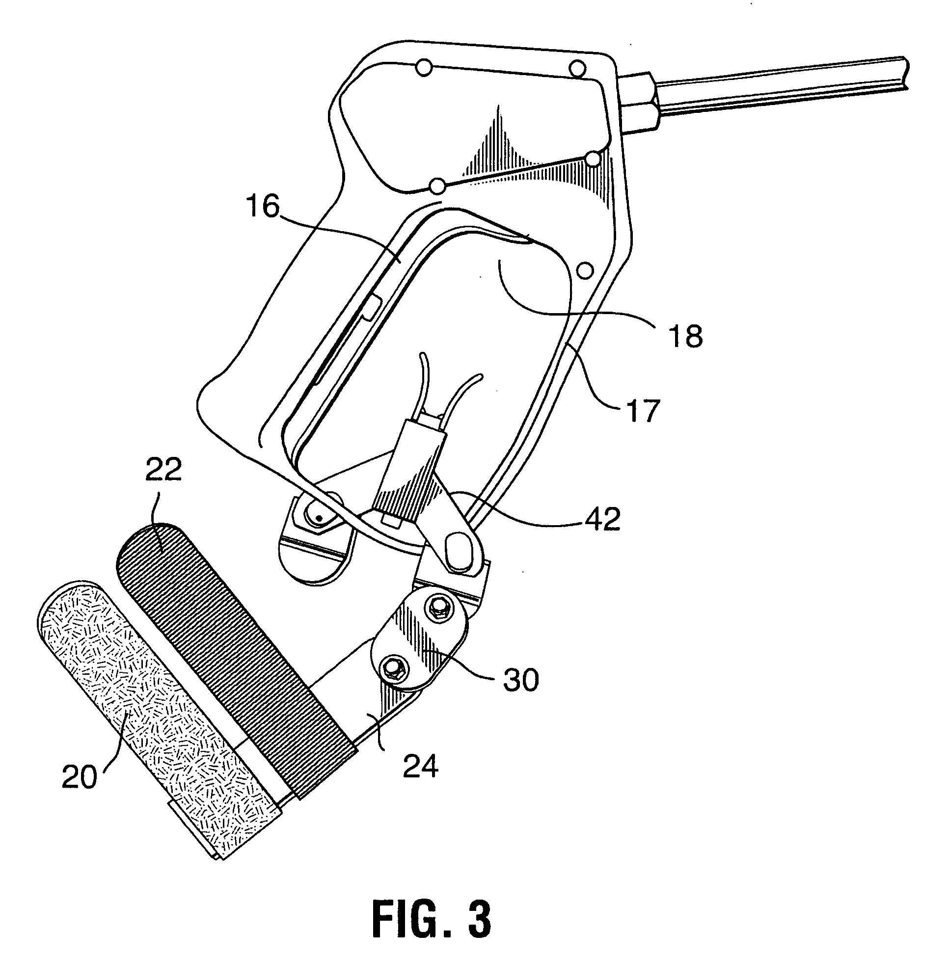
[0019]In accordance with FIGS. 1-5, the spray gun handle support and quick release trigger assembly 10 of the present invention, provides means to ease the use of a conventional spray gun by reducing stress and strain on the hand and wrist of a user.

[0020]As shown in FIG. 1, a conventional spray gun 12 is shown having a generally tubular housing 13 including a conduit for carrying a liquid therethrough (not shown), and a rear handle 14 portion angled downwardly therefrom. The spray gun 12 includes a tubular member 11 having a nozzle (not shown) extending from the front end 9 of the housing 13. The bottom end 7 of the handle portion 14 of the housing 13 includes an adapter means 8 for connecting a water line or hose such as a threaded nipple or HANSEN fitting connection. As illustrated in FIGS. 1, 3-5, the trigger guard 17 includes a front elongated portion 6 extending downward at an angle from the bottom front portion of the housing 13 and a bottom elongated portion 5 extending inwa...


PUM


Abstract

A spray gun handle support and quick release trigger assembly for use with a high pressure spray gun which includes an adapter for releaseable installation on a high pressure spray gun so that the trigger assembly holds the spray trigger in the on condition and the handle support provides an articulating brace adapter which is strapped to the user's arm and wrist to ease the stress of back pressure created by high pressure spray on the user's hand and wrist. The adapter utilizes two pivotally connected longitudinal members having at least one strap with hook and loop fasteners attached perpendicular to a first one of the longitudinal members for securing the brace to a forearm of the user. A spray gun handle support is pivotally attached to the distal end of a second one of the pivotal longitudinal members. The user holds the longitudinal members against the lower side of his forearm and fastens the hook and loop straps snugly around the forearm. The handle support body is inserted into and rotated within the spray gun handle and then the user grabs and holds the handle. In this position, the trigger is held on by the handle and the handle support body and brace provide support against the back pressure caused by the high pressure water spray.

Description

TECHNICAL FIELD[0001]The present invention relates to the field of high pressure spray guns and in particular to devices intended to be used with a spray gun to relieve stress and stain on the wrist and hand of the user.BACKGROUND OF THE INVENTION[0002]A power washer spray gun expels water at a high pressure for the purpose of cutting hard to remove dirt and debris from surfaces which are desired to be clean. The stream of water is at such a high pressure that accidental exposure to the stream could injure personnel or cause severe damage to soft surfaces. Therefore, it is absolutely necessary that a user maintains full and competent control of a spray gun. Because of the high pressure expulsion, a strong back pressure is produced against the hand and wrist of the spray gun user. After prolonged usage, a user will become tired or may suffer from muscle stress or strain due to the constant back pressure and the constant need to keep the trigger on the spray gun pressed. Eventually, t...

Claims


Application Information

Patent Timeline
IPC IPC(8): B05B15/06B05B9/01
CPCB05B9/01B05B15/061B05B12/002B05B15/63B05B15/62B05B12/0024
Inventor CROSSLEY, III, L.T. TOM
Owner CROSSLEY III L T TOM
Why Eureka
Try Eureka