
Artificial nose and breathing circuit provided with the artificial airway

a breathing circuit and artificial nose technology, which is applied in the direction of medical devices, combustion types, burners, etc., can solve the problems of disengagement, inability to supply an inspiratory gas to a person, and increasing the risk of a tube connection failure. , to achieve the effect of increasing the flow resistance and simple configuration

Inactive Publication Date: 2012-01-19
TKB
View PDF10 Cites 8 Cited by
  • Summary
  • Abstract
  • Description
  • Claims
  • Application Information

AI Technical Summary

Benefits of technology

[0041]As described above, an artificial airway and a breathing circuit of the present invention can achieve heating and humidification of an inspiratory gas sufficient for a user with a simple configuration without increasing the flow resistance (circuit resistance) of the inspiratory gas within the artificial airway, and further, being less affected by a change in temperature from the outside, and without developing condensation on the wall of the circuit.

Problems solved by technology

However, after passing through the container 134, the inspiratory gas is cooled to recondense the water vapor while passing through a breathing circuit (inspiratory tube) 102, so that there arises a problem of not being able to supply an inspiratory gas sufficiently heated and humidified to a person.
Further, it requires excessive devices and members, such as the container 134 for heating and humidification and the heater device 136, and also requires a disposable humidifier connecting tube 138 to link an inspiratory gas supply source (respirator) 122 and the container 134 for heating and humidification, so that there arises a problem of rising facility costs and running costs.
In addition, since connecting tubes are increased, there also arises a problem of increasing risks of a tube connection failure and disengagement of a tube.

Method used


Image

  • Artificial nose and breathing circuit provided with the artificial airway
  • Artificial nose and breathing circuit provided with the artificial airway
  • Artificial nose and breathing circuit provided with the artificial airway

Examples


Embodiment Construction

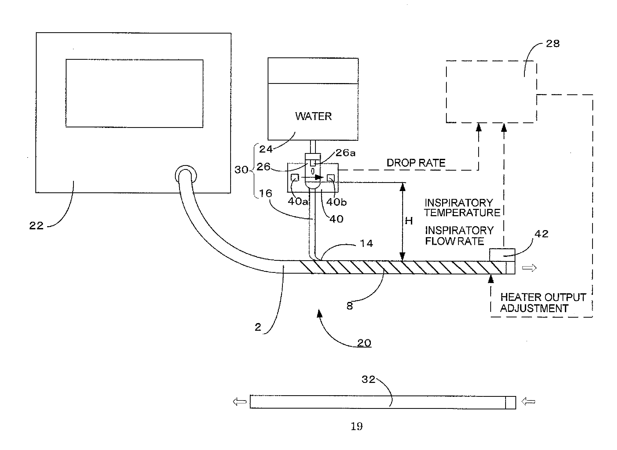
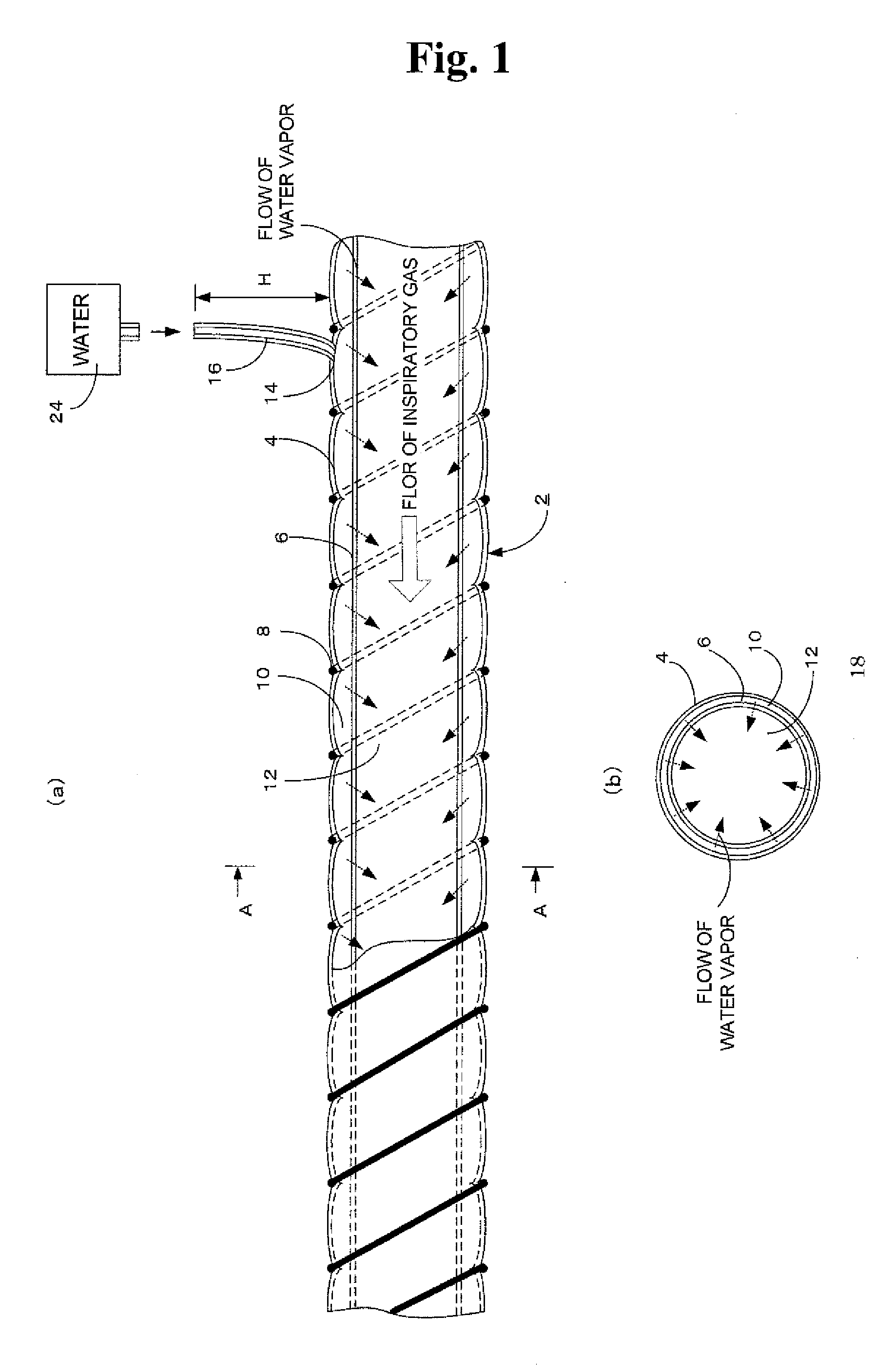
[0052]Embodiments of an artificial airway of the present invention used for a breathing circuit are described below with reference to the drawings. Here, FIGS. 1(a) and 1(b) are schematic views illustrating a structure of one embodiment of an artificial airway according to the present invention used for a breathing circuit, and

[0053]FIG. 2 is a schematic view illustrating a configuration of one embodiment of a breathing circuit provided with the artificial airway shown in FIGS. 1(a) and 1(b).

(Description of One Embodiment of Artificial Airway According to the Invention)

[0054]Firstly, with reference to FIGS. 1(a) and 1(b), a detailed description is given to one embodiment of an artificial airway according to the present invention. Here, FIG. 1(a) is a schematic view of an artificial airway 2 taken from a side and illustrates a state of eliminating an outer shell 4 to expose the inside from the center to the right side in the drawing. FIG. 1(b) is a cross-sectional view taken from arr...


PUM


Abstract

Provided is an artificial airway and a breathing circuit provided with the artificial airway, including a tubular outer shell; a moisture permeable and water resistant film disposed on an entire circumference of an internal surface of the outer shell, forming a water retention region with the outer shell, and forming an aeration region on an internal surface side thereof; a feed water inlet provided in the outer shell to supply water to the water retention region; and a heater disposed outside the outer shell, heating the water in the water retention region to generate water vapor, and also heating an inspiratory gas flowing in the aeration region, wherein the water supplied from the feed water inlet is retained in the water retention region by the moisture permeable and water resistant film, and only the water vapor generated by the heating of the heater passes through the moisture permeable and water resistant film and flows into the aeration region to heat and humidify the inspiratory gas flowing in the aeration region.

Description

TECHNICAL FIELD[0001]The present invention relates to an artificial airway and a breathing circuit provided with the artificial airway, and in particular, relates to an artificial airway and a breathing circuit to supply a heated and humidified inspiratory gas to a user.BACKGROUND ART[0002]In a case of carrying out artificial respiration using a breathing circuit provided with an artificial airway, an inspiratory gas supplied to a person is required to be heated and humidified in advance. To deal with this, as shown in FIG. 5, a container 134 for heating and humidification having water stored therein is normally heated with a heater device 136 to generate water vapor and to pass an inspiratory gas to be supplied to a person through the container 134, thereby heating and humidifying it. However, after passing through the container 134, the inspiratory gas is cooled to recondense the water vapor while passing through a breathing circuit (inspiratory tube) 102, so that there arises a p...

Claims


Application Information

Patent Timeline
IPC IPC(8): A61M16/16
CPCA61M16/1075A61M16/16A61M2205/3306A61M2205/3334A61M16/147A61M2205/3561A61M2205/50A61M16/1095A61M16/142A61M2205/3368A61M16/0051A61M16/162A61M16/145A61M16/021
Inventor SATA, YASUHIKOHACHISU, NORIO
Owner TKB
Learn More