
Backlight unit and display device including the same

Inactive Publication Date: 2012-01-12
SAMSUNG ELECTRONICS CO LTD
View PDF2 Cites 141 Cited by
  • Summary
  • Abstract
  • Description
  • Claims
  • Application Information

AI Technical Summary

Benefits of technology

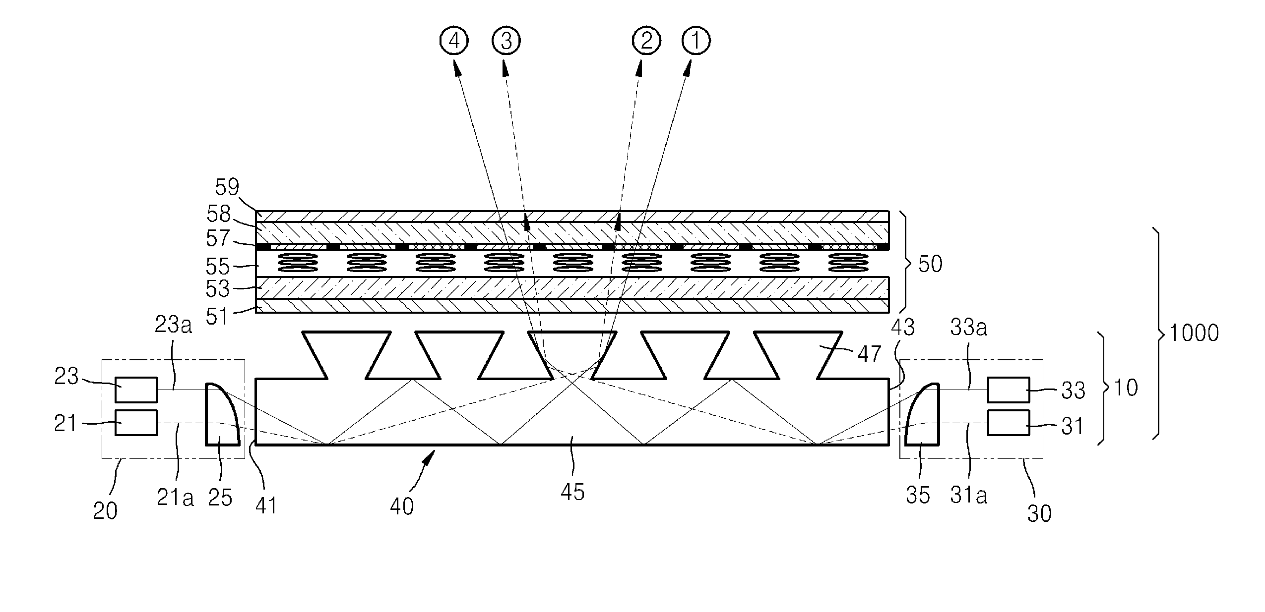
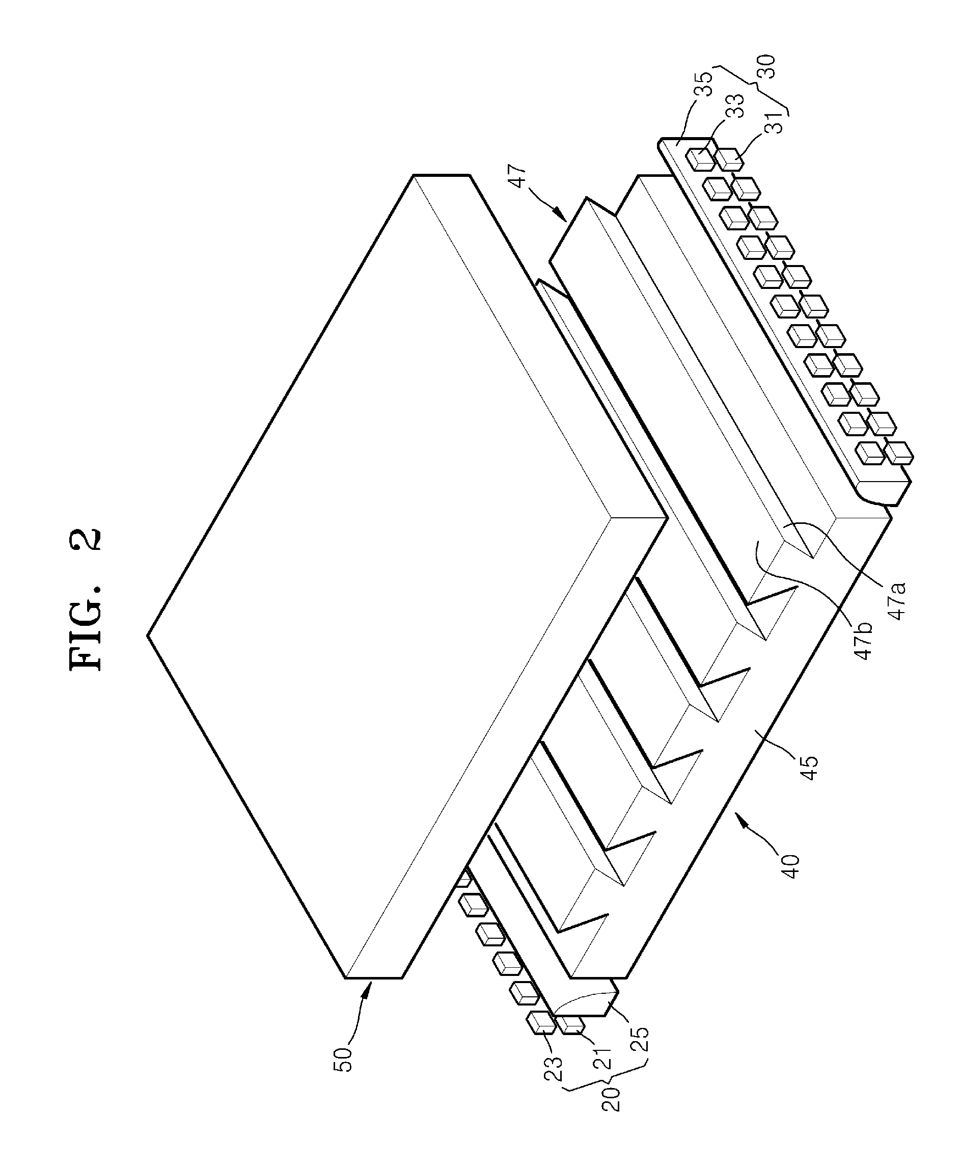
[0029]The backlight unit may provide collimated light and control a direction of the collimated light. Thus, by applying the backlight unit, a light exit direction may be quickly and sequentially controlled. Accordingly, a high-density directional (HDD) 3D display device may be implemented.

Problems solved by technology

However, backlight units may not be self-emitting devices.

Method used


Image

  • Backlight unit and display device including the same
  • Backlight unit and display device including the same
  • Backlight unit and display device including the same

Examples


Embodiment Construction

[0041]The following detailed description is provided to assist the reader in gaining an understanding of the methods, apparatuses, and / or systems described herein. Accordingly, various changes, modifications, and equivalents of the systems, apparatuses, and / or methods described herein will be suggested to those of ordinary skill in the art. In this regard, the described examples may have different forms and should not be construed as being limited to the descriptions set forth herein. Accordingly, the examples are merely described below, by referring to the figures, to explain aspects of the present description. Also, descriptions of well-known functions and constructions may be omitted for increased clarity and conciseness. As described herein, it is noted that terminology such as “totally internally reflected” is provided for descriptive purposes for the understanding of one of ordinary skill in the art; that is, it should be understood that such language is intended to indicate t...


PUM


Abstract

A backlight unit and a display device including the backlight unit are provided. The backlight unit includes at least one light source unit and a light guide plate. The light source unit provides collimated light and controls light such that it is emitted in a plurality of light exit directions.

Description

CROSS-REFERENCE TO RELATED APPLICATIONS[0001]This application claims the benefit of Korean Patent Application No. 10-2010-0066411, filed on Jul. 9, 2010, in the Korean Intellectual Property Office, the disclosure of which is incorporated herein in its entirety by reference.BACKGROUND[0002]1. Field[0003]The following description relates to backlight units and display devices including backlight units, and more particularly, to backlight units that provide collimated light.[0004]2. Description of the Related Art[0005]Backlight units (BLU) may supply light in liquid crystal display devices. However, backlight units may not be self-emitting devices.[0006]A general backlight unit emits radially spreading light, that is, Lambertian light, to a liquid crystal layer. Thus, luminance and colors of light that vary according to viewing angles, due to various lengths of an optical path of light that passes through the liquid crystal layer, need to be compensated for to produce a clear image for...

Claims


Application Information

Patent Timeline
IPC IPC(8): G02F1/13357F21V7/04
CPCG02B6/003G02B6/0073G02B6/0068G02B6/0038G02F1/1336G02F1/133606
Inventor MUN, YONG-KWEUNCHOI, YOON-SUNLEE, HONG-SEOK
Owner SAMSUNG ELECTRONICS CO LTD
Learn More