
Hydroprocessing catalysts and methods for making thereof

a technology of hydroprocessing catalysts and catalysts, applied in the field of catalysts, can solve the problems of increasing capital and operating costs, requiring a considerable amount of upgrading, and economic limitation as to the amount of catalysts that can be used, and achieve the effect of reducing metal deposits

Active Publication Date: 2012-01-05
CHEVROU USA INC
View PDF2 Cites 42 Cited by
  • Summary
  • Abstract
  • Description
  • Claims
  • Application Information

AI Technical Summary

Benefits of technology

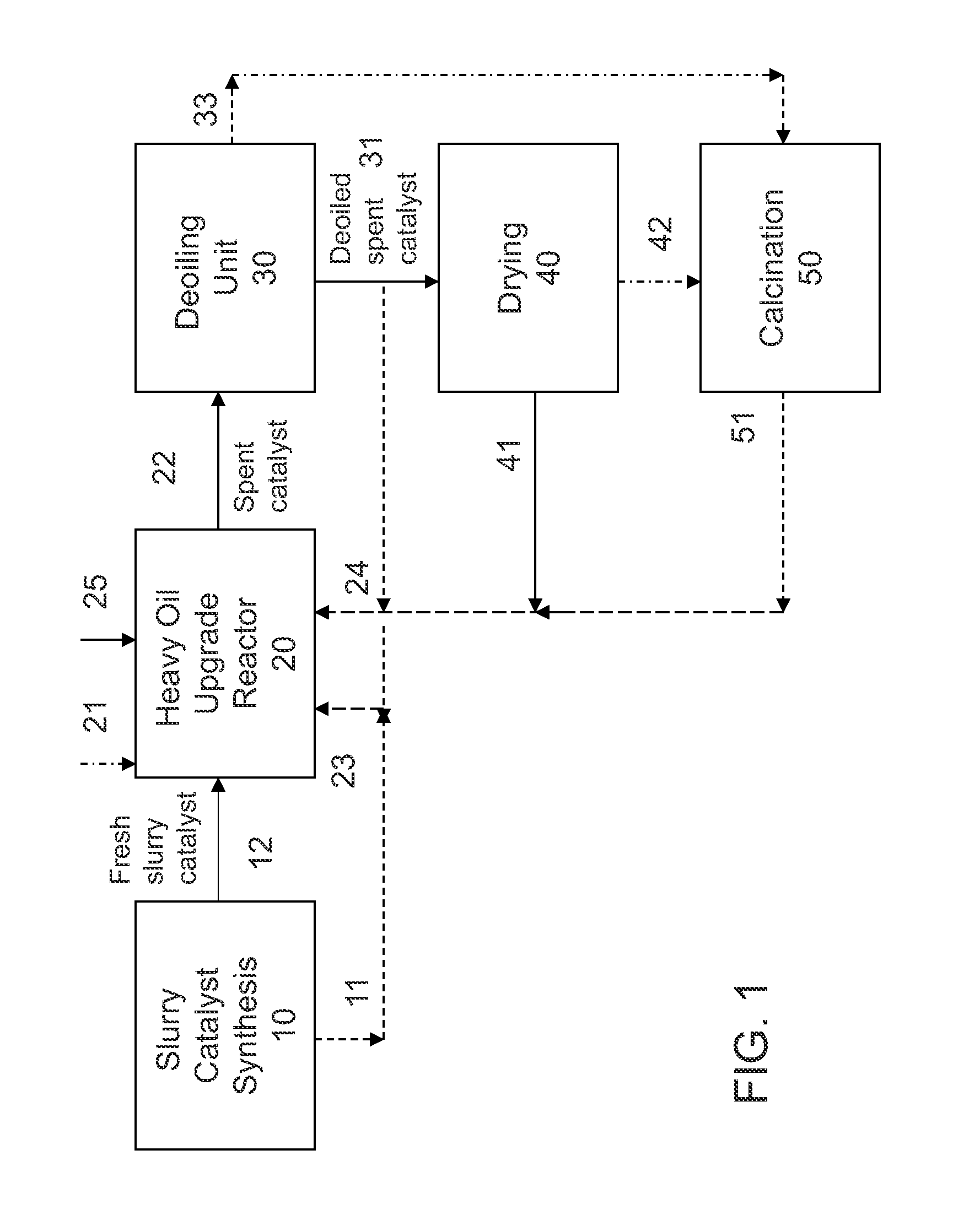
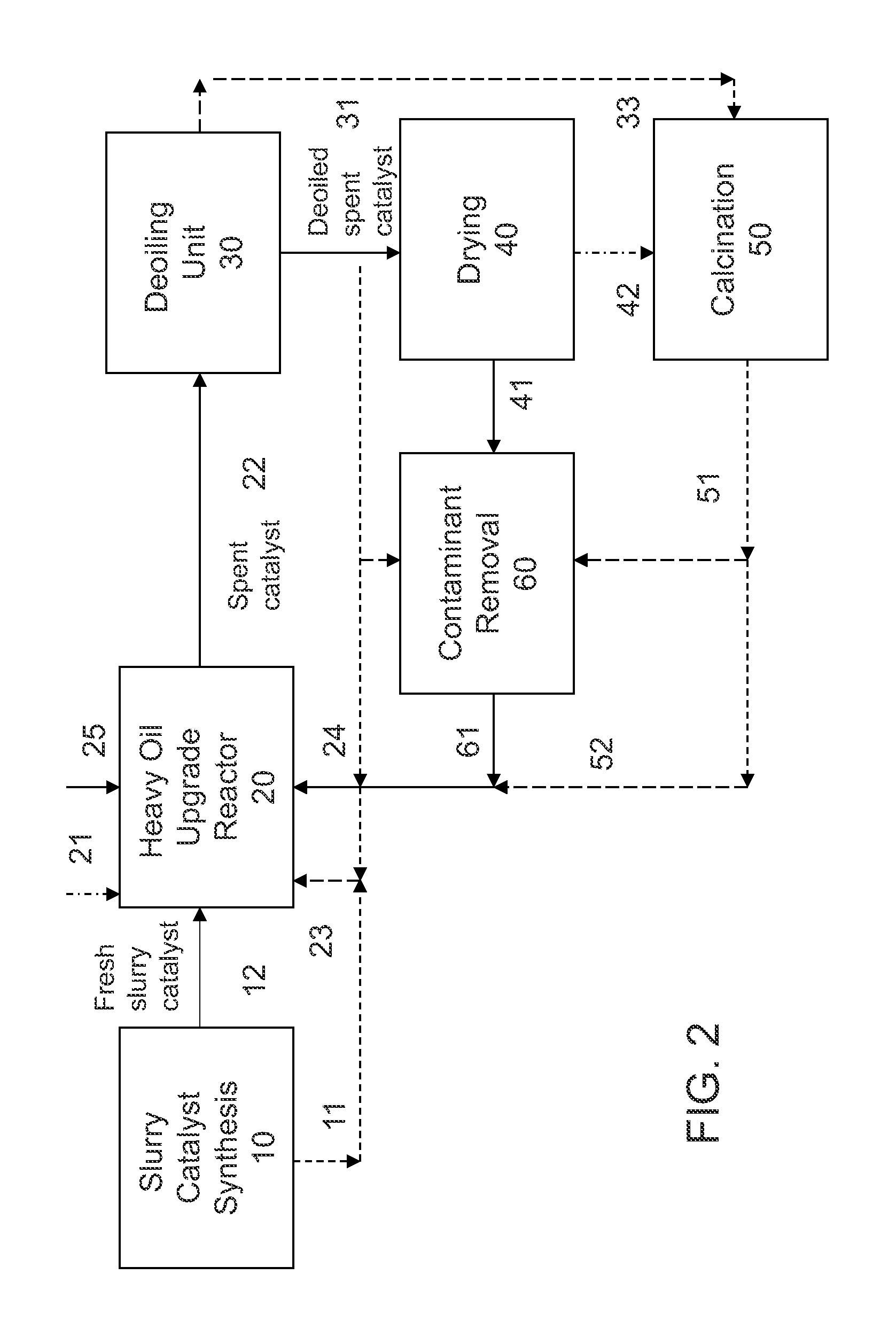
[0007]In one aspect, the invention relates to a catalyst feed system for use in the upgrade of heavy oil feedstock. The catalyst feed system comprises: a) a deoiled spent catalyst comprising a plurality of dispersed particles slurried in a hydrocarbon medium as a slurry, the deoiled catalyst retaining less than 80% bu...

Problems solved by technology

Feedstocks derived from these heavy materials contain more sulfur and nitrogen than feedstocks derived from more conventional crude oils, requiring a considerable amount of upgrading in order to obtain usable products therefrom.
These heavier and high sulfur crudes and resides also present problems as they invariably also contain much higher metals contaminant metals such as nickel, vanadium, and iron, which represent operating problems in terms of metal deposit / build-up in the equipment.
However, there is an economic limitation as how much catalyst can be used, as a high dosage will drive up capital and operating costs.

Method used


Image

  • Hydroprocessing catalysts and methods for making thereof
  • Hydroprocessing catalysts and methods for making thereof

Examples


example 1

[0086]A Ni—Mo slurry catalyst as described in U.S. Pat. Nos. 7,737,072 and 7,737,073 was used in a heavy oil upgrade process as described in U.S. Pat. No. 7,390,398. The catalyst was used at a high concentration of Mo relatively to VR feed (4 wt. % Mo to VR), so it is “lightly-deactivated” with ˜50% of the original catalytic activity (relative to a fresh catalyst). The spent catalyst underwent a deoiling step similar to the procedures described in US Patent Publication No. 20100163499, employing a combination of sedimentation and a cross-filtration system wherein a solvent is added to the filtration feed stream, generating a deoiled solids coke product containing metal sulfides. The deoiled spent catalyst was slurried in VGO or VGO-based fresh slurry catalyst, at a VGO to deoiled spent catalyst weight ratio of 2:1 to 20:1, forming a slurried catalyst (“SCS” or spent catalyst slurry).

example 2

[0087]A second Ni—Mo deoiled spent catalyst was generated as in Example 1, except that the catalyst was employed at a low concentration of Mo relative to heavy oil feed (0.5 wt. % Mo to VR), retaining less than ˜⅓ of the original catalytic activity. Table 1 summarizes the properties and characteristics of the deoiled spent catalyst samples. The deoiled spent catalyst was slurried in VGO or VGO-based fresh slurry catalyst, at a VGO to deoiled spent catalyst weight ratio of 2:1 to 20:1, forming a slurried catalyst (“SCS” or spent catalyst slurry).

TABLE 1Example 1Example 2CompositionMo, wt %39.2730.37Ni, wt %4.053.56V, wt %0.662.91C, wt %23.3534.28PorosimetrySA, m2 / g33.119.14TPV, cc / g0.1370.065PV (>100 Å), cc / g0.1090.062Particle Size DistributionMean Dp (volume-basis, sonic), μm8.229.0Mean Dp (number-basis, sonic), μm0.270.72

example 3

[0088]A third Ni—Mo deoiled spent catalyst was generated as in Example 1, an analysis of the spent catalyst solid shows 24.91 wt. % Mo, 4.42 wt. % Ni, and 6.22 wt. % V (primarily oxide form).


PUM


Abstract

A method to reduce metal deposit in the hydroprocessing or upgrade of heavy oil feedstock is provided. The method comprises feeding an improved catalyst feed to the system, with the improved catalyst feed comprising a fresh slurry catalyst and a deoiled spent catalyst, with the deoiled spent catalyst being present in an amount of at least 10% the catalyst feed for the heavy oil upgrade system to have at least a 5% reduction in metal contaminant build-up compared to heavy oil upgrade system without the deoiled spent catalyst in the feed.

Description

CROSS-REFERENCE TO RELATED APPLICATIONS[0001]This application claims benefit under 35 USC 119 of U.S. Provisional Patent Application No. 61 / 428,599 with a filing date of Dec. 30, 2010. This application is also continuation-in-part (CIP) of U.S. patent application Ser. No. 12 / 506,937 with a filing date of Jul. 21, 2009; a CIP of U.S. patent application Ser. No. 13 / 103,790 with a filing date of May 9, 2011. This application claims priority to and benefits from the foregoing, the disclosures of which are incorporated herein by reference.TECHNICAL FIELD[0002]The invention relates generally to catalysts for use in the conversion of heavy oils and residua and methods for making thereof.BACKGROUND[0003]The petroleum industry is increasingly turning to heavy crudes, resids, coals and tar sands as sources for feedstocks. Feedstocks derived from these heavy materials contain more sulfur and nitrogen than feedstocks derived from more conventional crude oils, requiring a considerable amount of ...

Claims


Application Information

Patent Timeline
IPC IPC(8): C10G65/10
CPCC10G47/02C10G47/26C10G47/32C10G47/36C10G65/00C10G2300/802C10G65/18C10G2300/205C10G2300/4075C10G2300/701C10G65/10
Inventor YANG, SHUWUCHABOT, JULIEREYNOLDS, BRUCE EDWARDKOU, BO
Owner CHEVROU USA INC
Learn More