Eureka AIR delivers breakthrough ideas for toughest innovation challenges, trusted by R&D personnel around the world.

System and method for producing hydrocarbons from a well

a well and hydrocarbon technology, applied in the direction of fluid removal, earth-moving drilling, borehole/well accessories, etc., can solve the problems of not being able to produce liquids to the surface naturally or economically, the lift performance of oil wells suffers, and the well cannot produce liquids to the surface. natural or economic, etc., to achieve easy transportation, reduce backpressure, and increase the pressure of liquid fluid

Active Publication Date: 2012-01-05
CHEVROU USA INC
View PDF9 Cites 6 Cited by
  • Summary
  • Abstract
  • Description
  • Claims
  • Application Information

AI Technical Summary

Benefits of technology

[0010]In some cases, the system can be provided as a modular system that can be relocated depending on the needs of the reservoir. In particular, the unloading unit, compressor, gas manifold, and pump can be disposed on one or more skids, so that each skid can easily be transported and re-used for producing hydrocarbons from different reservoir formations.
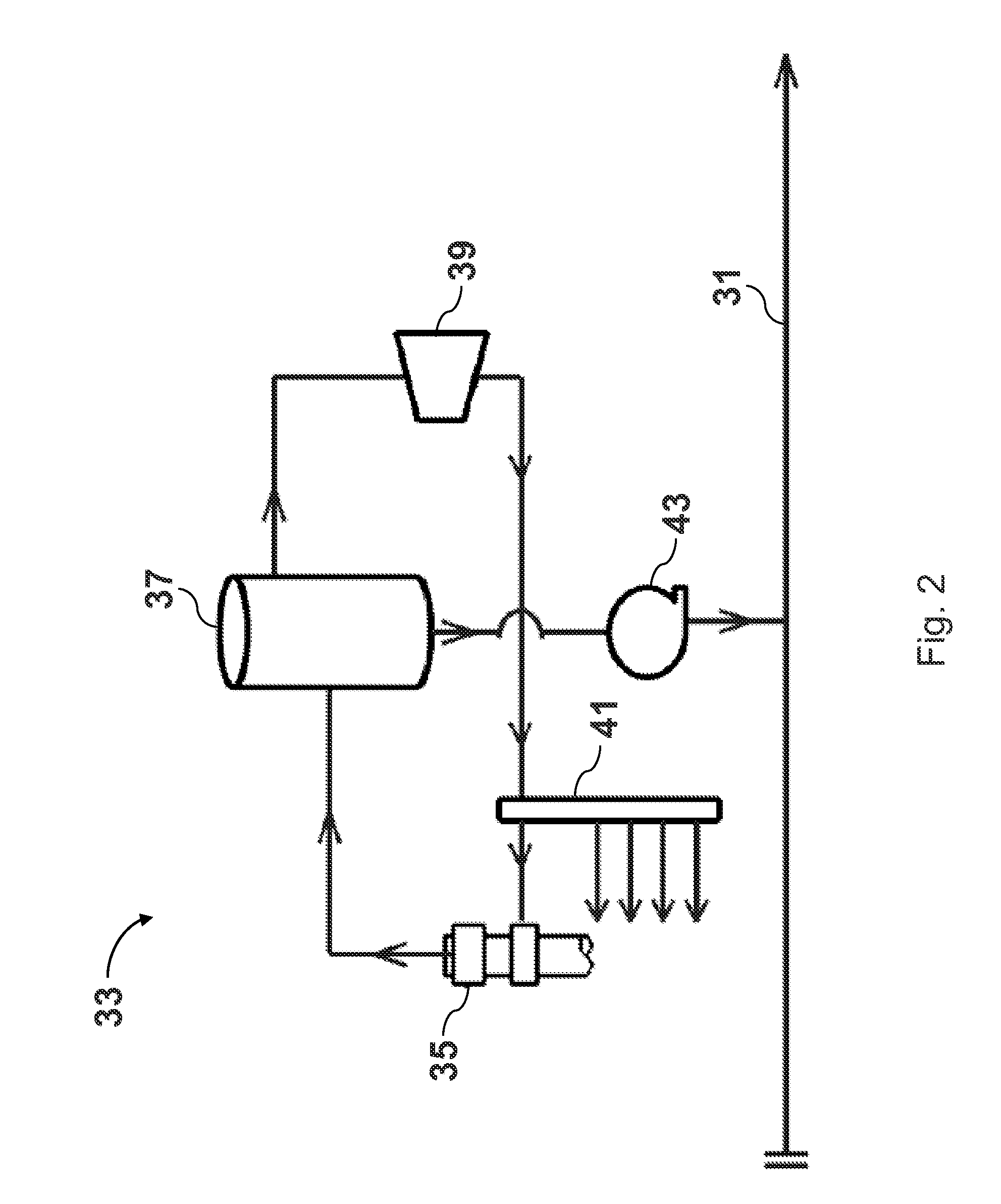
[0011]According to another embodiment, a method includes receiving in an unloading unit a produced fluid from the well and separating the produced fluid into a liquid fluid and a gas fluid. For example, the produced fluid can be separated kinetically, such as by a gas-liquid cylindrical cyclone, and / or water can be separated from the gas and liquid fluids. The gas fluid from the unloading unit is compressed to a predetermined pressure and distributed to at least one production tree and corresponding well. From the manifold, the gas fluid is re-injected into the well to help lift the produced fluid from the reservoir. Also, the fluid pressure of the liquid fluid is increased in a pump, and the liquid fluid is delivered to a pipeline, such as a subsea pipeline located on a seafloor. The effect of receiving the produced fluid and increasing the pressure of the liquid fluid can be to reduce the backpressure at the well.

Problems solved by technology

Moreover, each have inherent challenges, particularly in offshore environments where cost and space become important limitations.
As reservoir pressure declines due to depletion, the lift performance of oil wells suffers and at a certain point the well is no longer able to produce liquids to the surface naturally or economically because the pressure at the reservoir is not large enough to overcome the hydrostatic head of the fluids between it and the production tree at the platform.
The problem associated with the conventional well unloading unit process is that any gas produced is vented to the atmosphere and lost.
This is both an environmental concern and a lost production / revenue opportunity as the gas has value and could be sold.
This increases the drawdown on the well and increases both liquid rates and reserves.
The major problem with applying gas lift to a well is that high pressure gas is required, typically greater than 1000 psi.
Oftentimes, using high pressure gas from other wells is not an option for operations.
Additionally, even if there is a well with high pressure gas, it is only a short-term solution as reservoir pressures decline quickly and the gas pressure soon reaches a point where it is not adequate for gas lifting.
However, the problem with this option is the high cost, large footprint and immobility of compressors.
Additionally, the units are immobile—the cost to move a gas lift compressor from one platform to another is more expensive than the compressor itself.
If a platform does not warrant the installation of a gas lift compressor due to economics or spacial limitations, then hydrocarbons are typically left behind in the reservoir.

Method used


Image

  • System and method for producing hydrocarbons from a well
  • System and method for producing hydrocarbons from a well
  • System and method for producing hydrocarbons from a well

Examples


Embodiment Construction

[0017]The present invention now will be described more fully hereinafter with reference to the accompanying drawings, in which some, but not all embodiments of the invention are shown. Indeed, this invention may be embodied in many different forms and should not be construed as limited to the embodiments set forth herein; rather, these embodiments are provided so that this disclosure will be thorough and complete, and will fully convey the scope of the invention to those skilled in the art. Like numbers refer to like elements throughout.

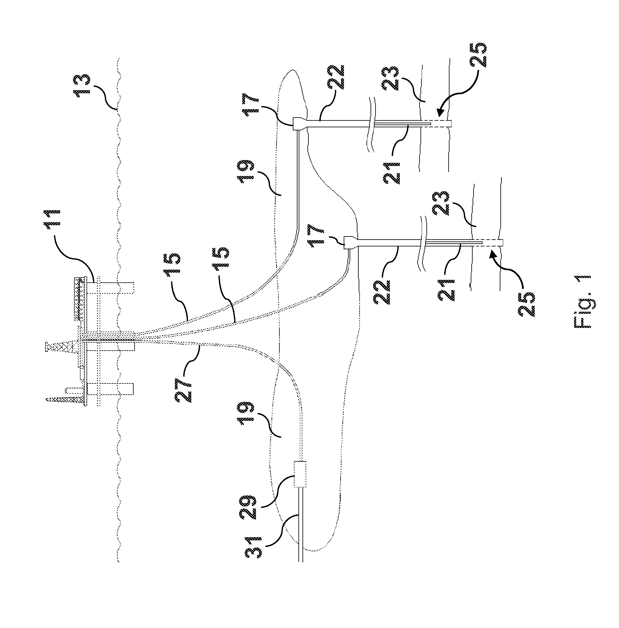
[0018]Referring to FIG. 1, an offshore oil production platform 11 is shown at the surface 13 of the sea. Platform 11 is shown as a floating platform, but is merely meant to be representative for any offshore oil platform known in the art, such as jack-up or tension leg platforms. Risers 15 extend from platform 11 to subsea wellheads 17. Wellheads 17 are located at the sea floor 19. Wellheads 17 are positioned above, and in fluid communication with, a...


PUM


Abstract

A system for producing hydrocarbons from a well includes an unloading unit that receives fluids from a wellhead. The unloading unit separates the oil and gas, and the oil is pumped to a pipeline. Using the unloading unit and the pump helps to reduce the pressure at the wellhead which helps increase production. The gas separated by the unloading unit is compressed and re-injected into the well to create a gas lift which further helps increase production. Capturing and reinjecting the separated gas for gas lift operations reduces environmental damages associated with conventional unloading unit and pump assemblies. The unloading unit, compressor, and pump are modular for quicker installation and a smaller footprint. After increasing the productive life of a first reservoir, the system can be broken down and reassembled for use at another reservoir.

Description

RELATED APPLICATIONS[0001]This application is related to and claims priority to U.S. provisional application No. 61 / 360,235 filed on Jun. 30, 2010.FIELD OF THE INVENTION[0002]The present invention is generally related to hydrocarbon production, and more particularly, to producing hydrocarbons with the assistance of artificial lift.BACKGROUND OF THE INVENTION[0003]Two forms of artificial lift that help prolong the life of hydrocarbon wells are the use of gas lift and well unloading units. These two forms of artificial lift are common knowledge in the industry and are applied around the world. Moreover, each have inherent challenges, particularly in offshore environments where cost and space become important limitations.[0004]As reservoir pressure declines due to depletion, the lift performance of oil wells suffers and at a certain point the well is no longer able to produce liquids to the surface naturally or economically because the pressure at the reservoir is not large enough to o...

Claims


Application Information

Patent Timeline
Patent Type & Authority Applications(United States)
IPC IPC(8): E21B43/00
CPCE21B43/121E21B43/36E21B43/122
Inventor REXILIUS, JARRADWAMANON, TIPPARATSAHNI, AKSHAY
Owner CHEVROU USA INC
Why Eureka
Eureka Blog
Learn More