Microphone Interference Detection Method and Apparatus

Inactive Publication Date: 2011-12-29
GOOGLE TECH HLDG LLC
View PDF3 Cites 151 Cited by
  • Summary
  • Abstract
  • Description
  • Claims
  • Application Information

AI Technical Summary

Problems solved by technology

A risk of not reducing the gain is that the recorded audio signal will exhibit microphone clipping.
Like mechanical interference, microphone occlusion is most likely caused by the user of the electronic device 100.

Method used


Image

  • Microphone Interference Detection Method and Apparatus
  • Microphone Interference Detection Method and Apparatus
  • Microphone Interference Detection Method and Apparatus

Examples


Embodiment Construction

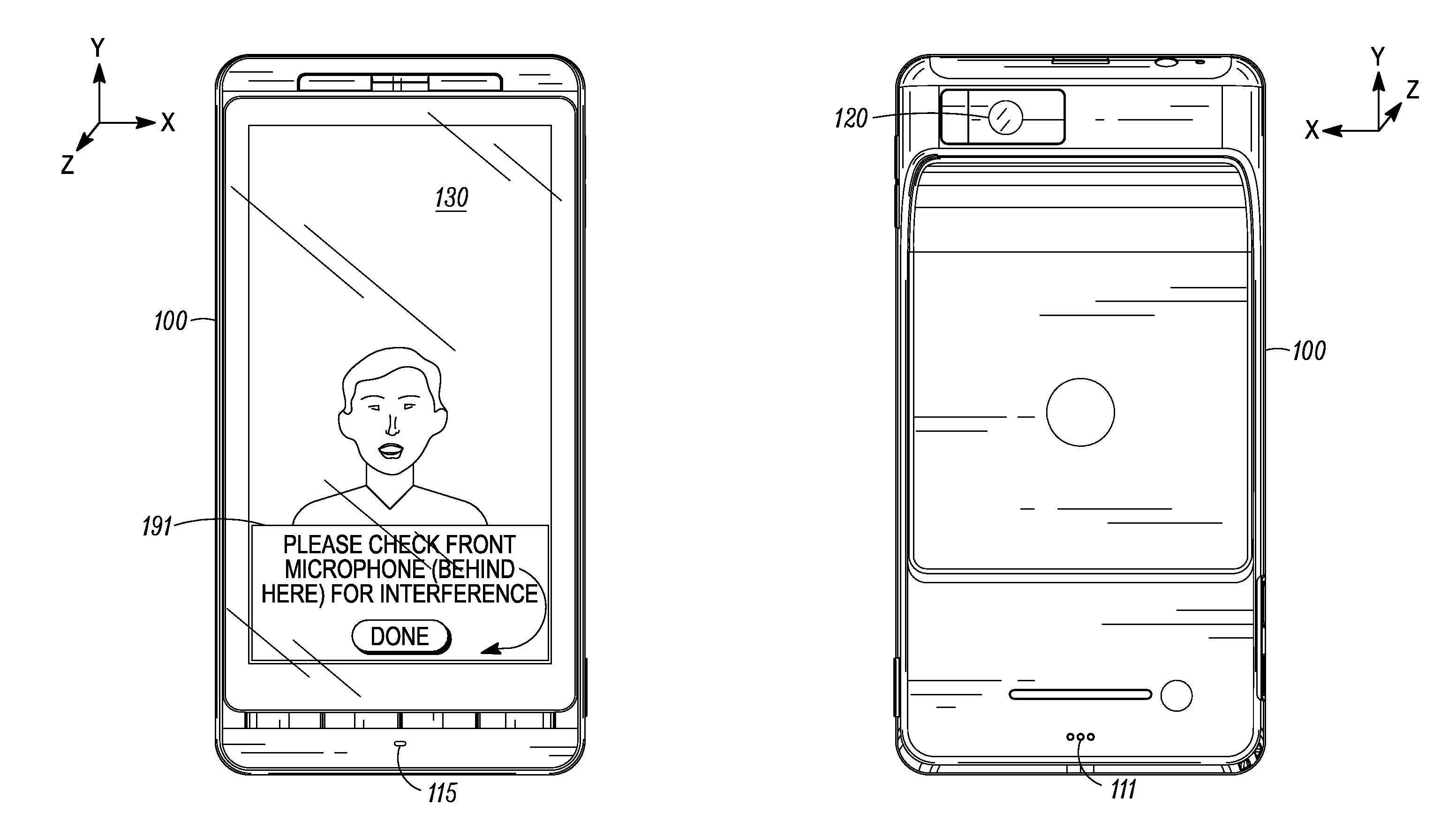
of FIG. 1 displaying a third notice regarding possible microphone interference.

[0010]FIG. 6 shows the example electronic device of FIG. 1 displaying a fourth notice regarding possible microphone interference.

DETAILED DESCRIPTION

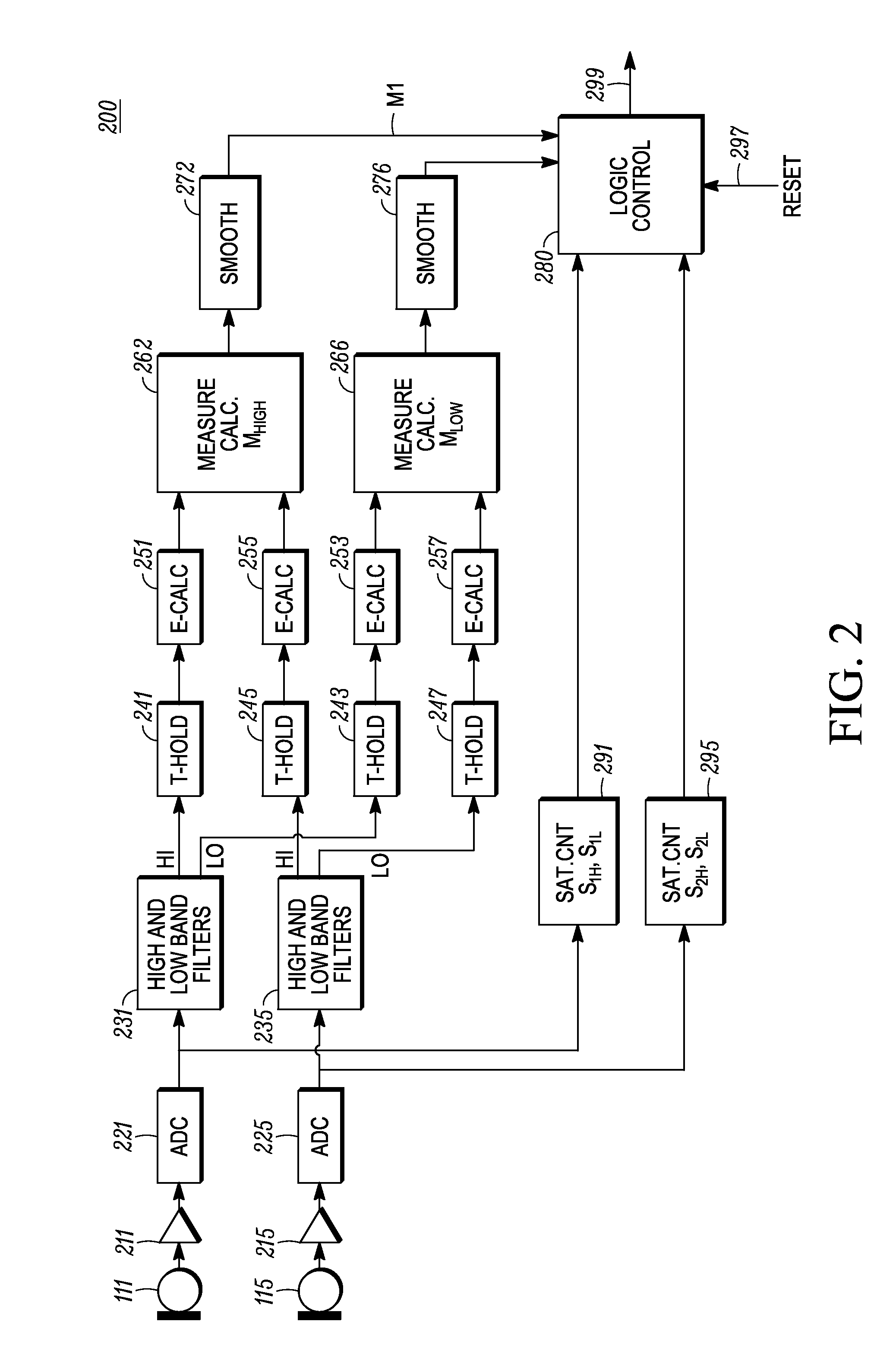
[0011]A method and apparatus for detecting microphone interference includes a first built-in microphone producing a first microphone signal and a second built-in microphone producing a first microphone signal. A first filter bank creates a first high-frequency-band signal and a first low-frequency-band signal from the first microphone signal. A second filter bank creates a second high-frequency-band signal and second low-frequency-band signal from the second microphone signal. A first measurement calculator determines a high-frequency-band energy value from the first high-frequency-band signal and the second high-frequency-band signal when the first high-frequency-band signal's magnitude exceeds a predetermined first threshold and the second high-frequency-ba...


PUM


Abstract

A method and apparatus for detecting microphone interference includes first and second built-in microphones producing first and second microphone signals. A first filter bank creates first high-frequency-band and first low-frequency-band signals from the first microphone signal. A second filter bank creates second high-frequency-band and second low-frequency-band signals from the second microphone signal. A first measurement calculator determines a high-frequency-band energy value from the first high-frequency-band signal and the second high-frequency-band signal when the first and second high-frequency-band signals' magnitudes exceeds predetermined thresholds. A second measurement calculator calculates a low-frequency-band energy value from the first low-frequency-band signal and the second low-frequency-band signal when the first and second low-frequency-band signals' magnitudes exceed predetermined thresholds. A logic control block, coupled to the first measurement calculator and the second measurement calculator, detects microphone interference and produces an output signal indicating microphone occlusion or wind noise.

Description

FIELD OF THE DISCLOSURE[0001]This disclosure relates generally to audio recording by portable electronic devices with built-in microphones.BACKGROUND OF THE DISCLOSURE[0002]A port of a built-in microphone of a portable electronic device has a fixed location on the device housing. Generally, the built-in microphone port is visually unobtrusive and a user may inadvertently interfere with an audio recording by placing a hand or finger over the microphone port, rubbing or tapping on the microphone port, subjecting the microphone to unintended wind noise, or subjecting the microphone to too much background noise. More than one microphone port on the device housing increases the chances of a user unintentionally creating microphone interference.[0003]Sometimes these types of microphone interference might be remedied easily by the user. Unfortunately, the user may be unaware of the interference until the user plays back the recorded audio. At playback time, however, it is too late to remed...

Claims


Application Information

Patent Timeline
IPC IPC(8): H04B15/00
CPCH04R2410/07H04R3/005H04R3/00H04R1/08H04R3/04
Inventor IVANOV, PLAMEN A.MEHRENS, SCOTT A.BASTYR, KEVIN J.CLARK, JOEL A.
Owner GOOGLE TECH HLDG LLC
Why Eureka
Try Eureka