
Hydrodynamic chamfer thrust bearing

a technology of chamfer and thrust bearing, which is applied in the direction of piston pumps, vessel construction, marine propulsion, etc., can solve the problems of cardiac pumps, axial stiffness of stators that are not capable of counteracting axial forces on rotors, and can cause problems such as wear on rotors and casings, as well as problems affecting the performance of axial thrust bearings

Active Publication Date: 2011-12-22
HEARTWARE INC
View PDF5 Cites 34 Cited by
  • Summary
  • Abstract
  • Description
  • Claims
  • Application Information

AI Technical Summary

Benefits of technology

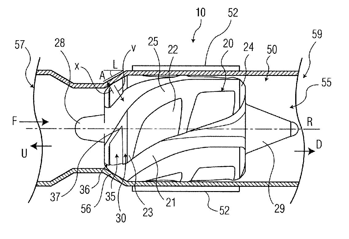
As further explained below, the downstream forces applied to the rotor through the hydrodynamic thrust bearing surfaces helps to offset the forces tending to move the rotor upstream during operation.

Problems solved by technology

However, the forces associated with axial flow cardiac pumps can present problems.
Under certain flow conditions, especially at lower flow volumes and / or higher rotational speeds, the axial stiffness of the stator may not be capable of counteracting the axial forces on the rotor.
Such contact can cause wear on the rotor and casing, which in turn can shorten the life of the pump and cause other undesirable effects.

Method used


Image

  • Hydrodynamic chamfer thrust bearing
  • Hydrodynamic chamfer thrust bearing
  • Hydrodynamic chamfer thrust bearing

Examples


Embodiment Construction

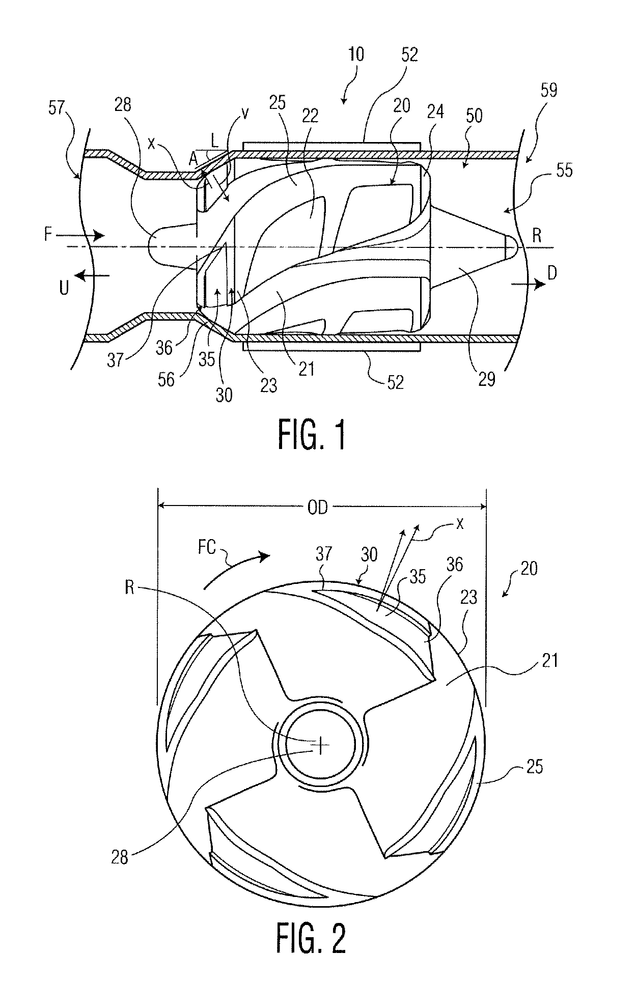
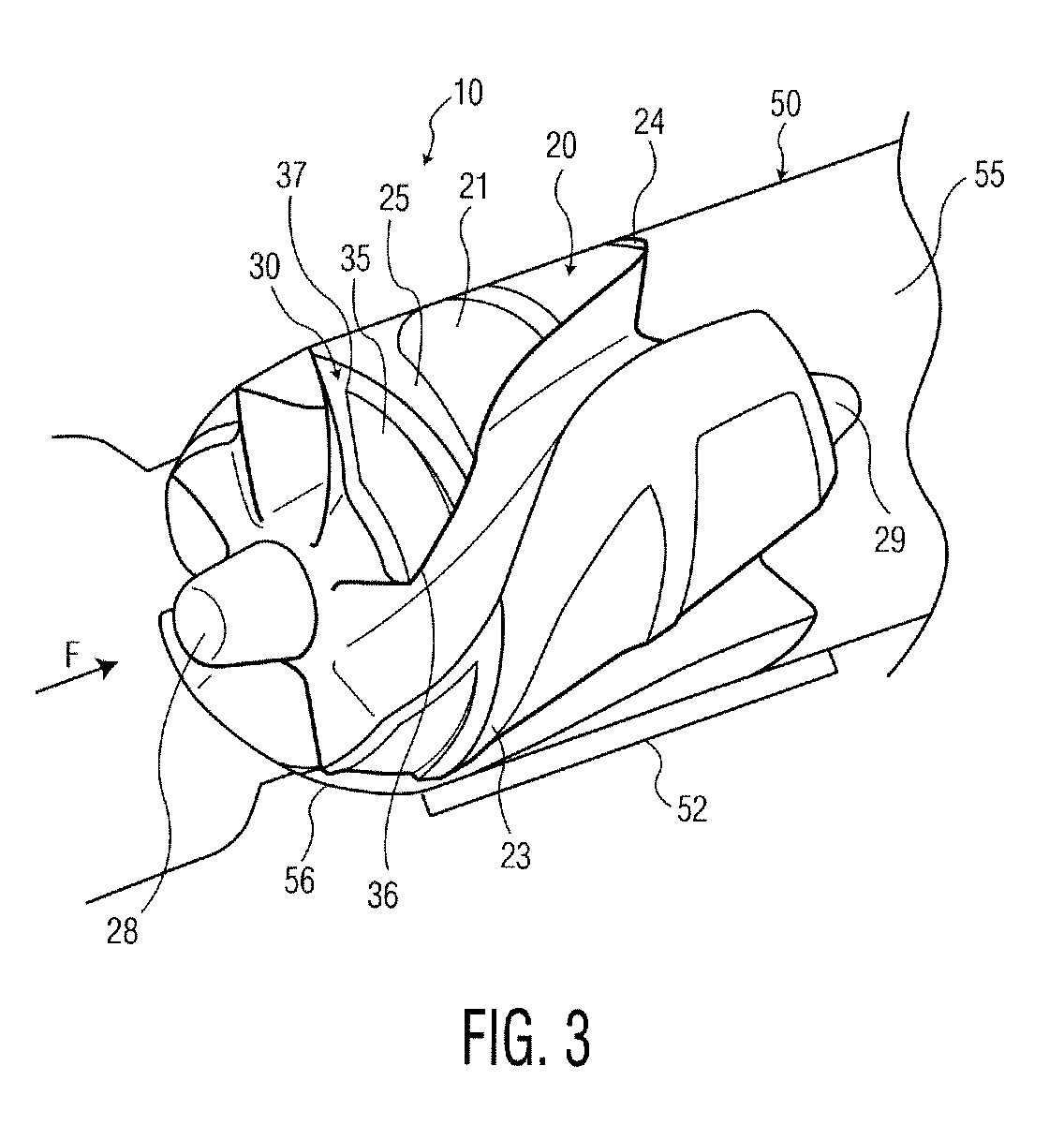
A blood circulating pump 10 according to first embodiment of the present invention, illustrated in FIGS. 1-3, includes a rotor having body 20. The body 20 is magnetic and biocompatible, and further includes an upstream end 23, a downstream end 24 and an axis R extending between the ends. The body 20 further includes a plurality of vanes 25 defining a plurality of channels 21 therebetween. The rotor body 20 is constructed and arranged to impel blood downstream, in the direction of fluid flow F, upon rotation of the rotor about axis R in a forward circumferential direction FC (FIG. 2). In the particular embodiment depicted, the forward circumferential direction FC is the clockwise direction as seen in FIG. 2, looking downstream towards the upstream end of the rotor.

Each vane 25 includes at least one hydrodynamic thrust bearing surface 35. As further explained below, each thrust bearing surface 35 is constructed and arranged to apply a hydrodynamic force V (FIG. 1) to the rotor with a ...


PUM


Abstract

An axial flow pump for a blood circulating pump for the circulation of blood, the rotor the rotor being constructed and arranged to impel blood in a downstream direction upon rotation of the rotor about its axis in a forward circumferential direction. The rotor is provided with hydrodynamic thrust bearing surfaces, each such thrust bearing surface being constructed and arranged to apply a hydrodynamic force to the rotor with a component of the force in the downstream direction upon rotation of the rotor in the forward circumferential direction.

Description

BACKGROUND OF THE INVENTIONThis application claims the benefit of U.S. Provisional Application No. 61 / 397,972, filed Jun. 18, 2010, the contents of which are hereby incorporated by reference into this application.Heart pumps are typically used in the later stages of heart disease or after trauma to the heart, when the heart itself is too weak or otherwise incapable of creating sufficient blood pressure and blood circulation to satisfy body function.Various heart pumps are already in use for the purpose of augmenting or replacing the blood pumping action of damaged or diseased hearts. Heart pumps are commonly used in three situations: (1) for acute support during cardio-pulmonary operations; (2) for short-term support while awaiting recovery of the heart from surgery; or (3) as a bridge to keep a patient alive while awaiting heart transplantation. The pumps may be designed to provide at least one of right or left ventricular assist, although left ventricular assist is the most common...

Claims


Application Information

Patent Timeline
Patent Type & Authority Applications(United States)
IPC IPC(8): F04B17/03F01D25/16
CPCF04D29/0413F04D29/181A61M1/1017Y10S415/90A61M1/101A61M60/824A61M60/422A61M60/148A61M60/237A61M60/135
Inventor WHITE, DANIEL G.
Owner HEARTWARE INC
Learn More