Method and apparatus for passive determination of target data

a target data and target technology, applied in direction finders, instruments, acoustic wave reradiation, etc., can solve the problems of incompletely unrealistic or illogical, unrealistic or illogical calculation methods, and sometimes unrealistic or illogical tma estimates of target data, so as to improve the reliability of this edge test method

Inactive Publication Date: 2011-12-22
ATLAS ELEKTRONIC GMBH
View PDF26 Cites 13 Cited by
  • Summary
  • Abstract
  • Description
  • Claims
  • Application Information

AI Technical Summary

Benefits of technology

[0040]Both the limit values and the state limit values derived from them are compared with the solution of at least one optimization method during the edge test, in order to determine whether the target data of the solution is within this solution space covered by the limit values, or on its “edge”. The test of limit values and state limit values derived from them advantageously improves the reliability of this edge test method.

Problems solved by technology

One such method, which is also referred to as target motion analysis (TMA), has the disadvantage, however, that the calculated solution may be unrealistic because of unknown disturbances in the received signals.
If the input data is received with major errors, the TMA method sometimes estimates unrealistic or illogical target data, such as a velocity of 80 knots or a departing course, even though the target is on an approaching course.
Completely unrealistic or illogical results, such as a range of 1000 kilometres, which can invariably occur in the iteration process when the received signals are subject to heavy noise, are excluded from the start.
However, the known CTMA method has the disadvantage that its optimized solution cannot converge with the actually correct solution if the limit values are chosen incorrectly.
Since the CTMA solution corresponds to the global minimum of an optimization criterion within the defined limit values, this does not produce the actually correct solution when the actual solution is outside the solution space defined by the limit values.

Method used


Image

  • Method and apparatus for passive determination of target data
  • Method and apparatus for passive determination of target data
  • Method and apparatus for passive determination of target data

Examples


Embodiment Construction

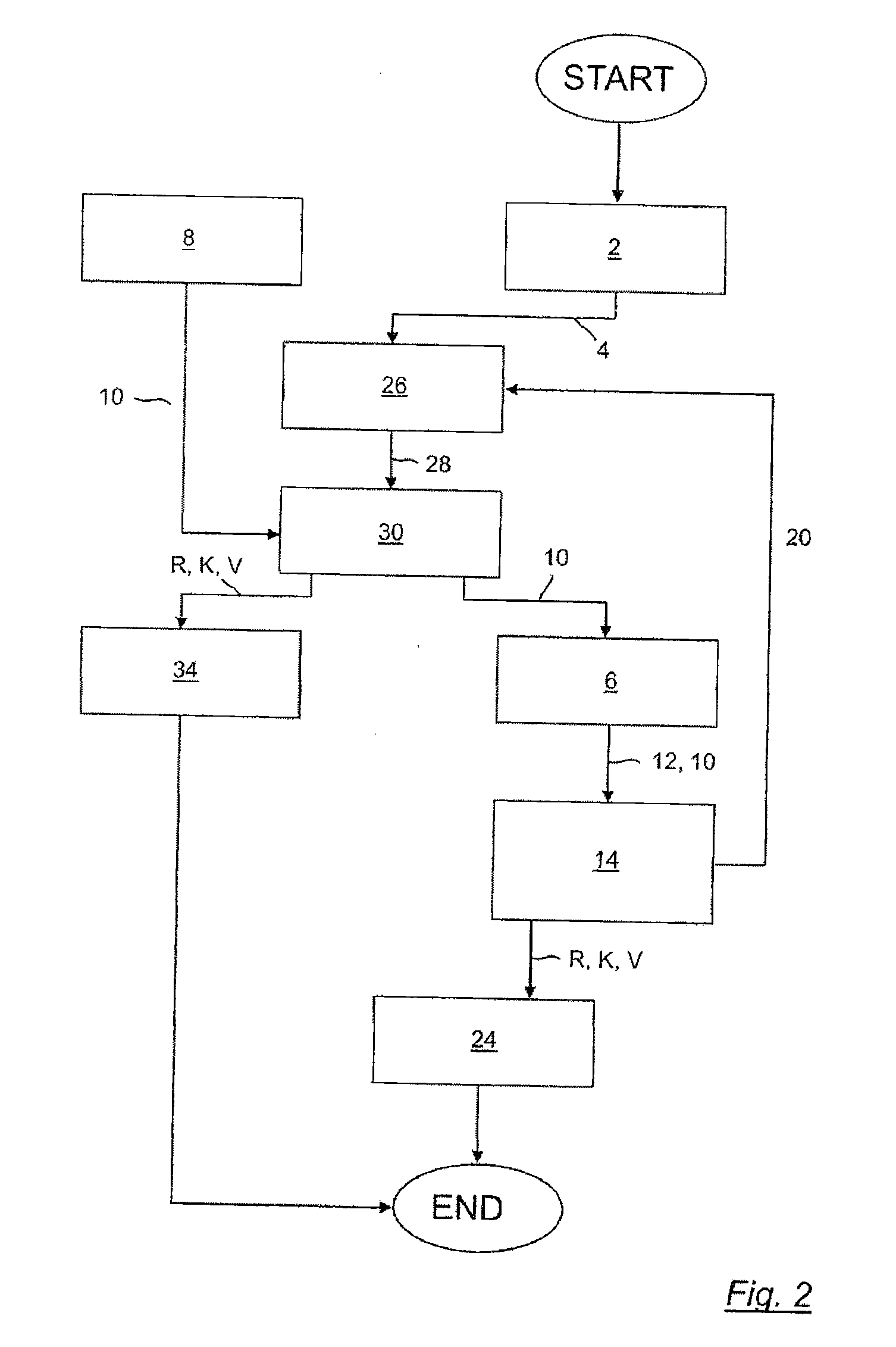
[0054]When a water craft is preferably moving at a constant velocity along its own leg, bearing angles to a target are measured from this water craft while the target is assumed to be moving with a constant velocity and on a constant course from a first target position to a second target position.

[0055]The bearing angles are determined in successive processing cycles as a function of the own position of the water craft. A position of the target is estimated from these bearing angles, and an associated estimated bearing angle is calculated. An optimization method is used to iteratively reduce the sum of the squares of the differences between the measured and estimated bearing angles over a plurality of processing cycles, until a predetermined error limit is undershot. An optimized solution of the optimization method is determined from the estimated position of the target on which the minimum is based. Target data, in particular a target range R, a target course K and / or a target velo...


PUM


Abstract

A method and apparatus for passive determination of target data (R, K, V) associated with a target from measured and estimated bearing angles. The measured bearing angles (4) are determined by a sonar receiving installation (2) by directionally selective reception of sound waves which are emitted or sent from a target, and the estimated bearing angles are determined from estimated positions of the target. The bearing angle differences from estimated and measured bearing angles are minimized iteratively over a plurality of processing cycles, and a position of the target, on which the minimum is based, is determined as the optimized solution (12). Furthermore, limit values (10) are defined for the target data (R, K, V) to be determined, in order to exclude unrealistic target data as solutions. However, because the optimized solution (12) from the optimization method (6) does not converge with the actual solution if the limit values (10) are chosen erroneously, an error handling process (14) for identification and correction of incorrect limit values (10) is carried out.

Description

CROSS-REFERENCE TO RELATED APPLICATION[0001]The present application claims the priority of European patent Application No. 10400031.0, filed Jun. 19, 2010, the subject matter of which, in its entirety, is incorporated herein by reference.BACKGROUND OF THE INVENTION[0002]The invention relates to a method for passive determination of target data associated with a target from measured and estimated bearing angles of the type mentioned in the precharacterizing clause of claim 1, to an apparatus for carrying out the method according to claim 10, and to a computer program which has suitable program code means for carrying out the method.[0003]In order to determine the range, velocity and course of a target, for example of a surface vessel, a submarine or of a torpedo, as target data associated with the target from a carrier vehicle, for example a surface vessel or a submarine, without giving itself away, a sonar receiving installation is used to receive sound waves of the target noise, an...

Claims


Application Information

Patent Timeline
Patent Type & Authority Applications(United States)
IPC IPC(8): G01S5/18
CPCG01S3/8086G01S3/8083
Inventor STEIMEL, ULRICH
Owner ATLAS ELEKTRONIC GMBH
Why Eureka
Try Eureka