
Canister with heater

Active Publication Date: 2011-12-22
KOREA FUEL TECH
View PDF9 Cites 19 Cited by
  • Summary
  • Abstract
  • Description
  • Claims
  • Application Information

AI Technical Summary

Benefits of technology

[0028]The present invention has been made in an effort to solve the above-described problems associated with prior art, and an object of the present invention is to provide a canister with a heater which can supply heat, required for desorption of fuel gas adsorbed onto active carbon filled in the canister, to the entire active carbon, thus improving the desorption efficiency of the active carbon.
[0029]Moreover, another object of the present invention is to provide a canister with a heater which can reduce the power consumption of the heater, provided to improve the desorption efficiency of the canister, to a minimum level, thus improving the fuel efficiency of a vehicle.

Problems solved by technology

The fuel gas contains harmful components such as hydrocarbon (HO) and the like, and thus, if the fuel gas is discharged to the outside of the vehicle, the air is polluted and the fuel is wasted.
However, the above-described canister has a problem that the temperature of the air heated by the heater is not greater than 100° C. and the actual temperature of the air heated and supplied to the active carbon is maintained at about 80° C.
Moreover, the heat of the air heated and supplied to the active carbon is absorbed by the active carbon around an inlet port thereof such that the heat is not uniformly distributed to the entire active carbon.
As a result, the desorption efficiency of the canister by the heated air is insignificant, which just meets the partial zero emission vehicle (PZEV) standards for exhaust emissions.
However, since the heat is supplied only to the active carbon being in contact with the discharge pipe, the heat is absorbed by the corresponding active carbon, and thereby the heat is not supplied to the entire active carbon.
As a result, the desorption efficiency of the canister is insignificant, which just meets the partial zero emission vehicle (PZEV) standards for exhaust emissions.
However, the temperature of the heat generated by the heat storage material filled in the chamber during desorption reaction does exceed a predetermined temperature, and thus the canister does not satisfy the desorption rate required by the hybrid vehicle.
Moreover, when the air is heated by the heater, in the case of the hybrid vehicle powered by both gasoline and electricity, the heater consumes excessive power, reducing the fuel efficiency of the vehicle.

Method used


Image

  • Canister with heater
  • Canister with heater
  • Canister with heater

Examples


Embodiment Construction

[0047]Hereinafter, preferred embodiments in accordance with the present invention will be described with reference to the accompanying drawings. The preferred embodiments are provided so that those skilled in the art can sufficiently understand the present invention, but can be modified in various forms and the scope of the present invention is not limited to the preferred embodiments.

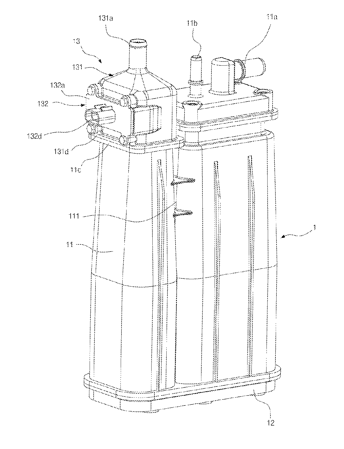
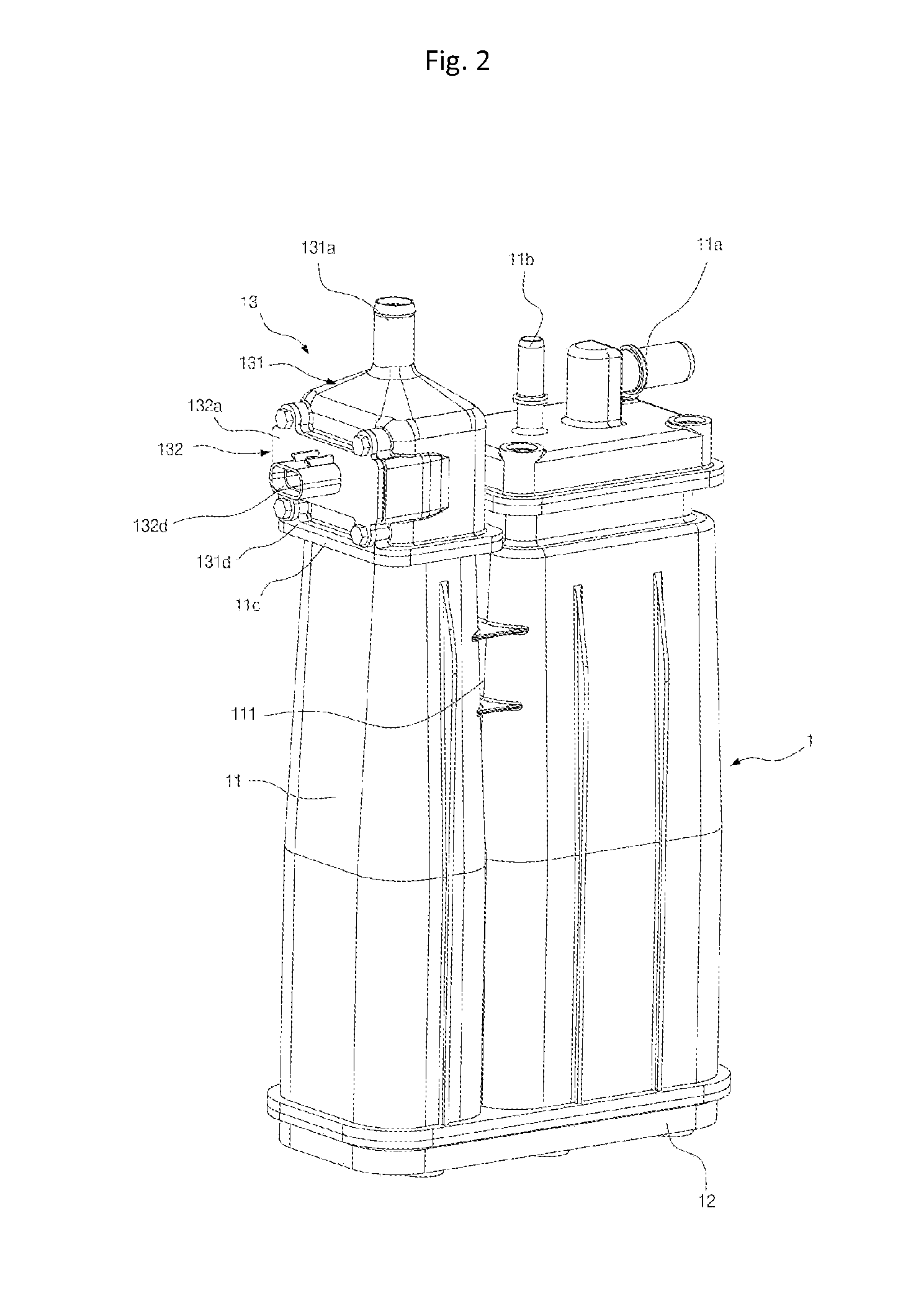
[0048]FIG. 2 is a perspective view of a canister with a heater according to a preferred embodiment of the present invention, FIG. 3 is a partially exploded perspective view of the canister of FIG. 2, FIG. 4 is a front cross-sectional view of the canister of FIG. 2, and FIG. 5 is a partially enlarged cross-sectional view of the canister of FIG. 2.

[0049]The canister 1 includes a canister housing 11 and a lower plate 12 connected to the bottom of the canister housing 11. A heater 13 is provided at the top of the canister housing 11.

[0050]Although not shown in the figures, a fuel gas reducing device, a dif...


PUM


Abstract

The present invention provides a canister mounted in a vehicle to reduce the discharge of fuel gas and, more particularly, a canister with a heater configured such that fuel gas adsorbed onto active carbon filled in the canister is more easily desorbed from the active carbon and introduced into an engine. The canister with the heater according to the present invention includes a canister housing including a tank port and a purge port, which are provided at the top thereof, and a plurality of inlet holes provided on one side thereof to introduce air; and a heater connected to the top of the plurality of inlet holes of the canister housing and including an air port provided at the top thereof, an open bottom, and a heater module provided therein.

Description

CROSS-REFERENCE TO RELATED APPLICATION[0001]This application claims the benefit of Korean Patent Application No. 10-2010-0058857, filed on Jun. 22, 2010, and Korean Patent Application No. 10-2010-0099075, filed on Oct. 12, 2010, the entire disclosures of which are hereby incorporated by reference.BACKGROUND OF THE INVENTION[0002]1. Field of the Invention[0003]The present invention relates to a canister mounted in a vehicle to reduce the discharge of fuel gas and, more particularly, to a canister with a heater configured such that fuel gas adsorbed onto active carbon filled in the canister is more easily desorbed from the active carbon and introduced into an engine.[0004]2. Description of Related Art[0005]Typically, an apparatus for storing fuel gas generated from a fuel tank and transferring it to an engine is employed in a vehicle, and such an apparatus is generally referred to a canister.[0006]Fuel required for driving the engine is stored in the fuel tank. When the fuel is evapor...

Claims


Application Information

Patent Timeline
IPC IPC(8): B01D53/02
CPCF02M25/0836F02M25/089F02M25/0854B60K15/03504B60K2015/03514B01D53/04B01D2259/4516
Inventor KIM, HYUN KIHWANG, TAE KYUCHOI, JOON YOUNG
Owner KOREA FUEL TECH
Learn More