
Method for wheel suspension measurement and a device for measuring the wheel suspension geometry of a vehicle

Active Publication Date: 2011-12-22
BEISSBARTH
View PDF10 Cites 6 Cited by
  • Summary
  • Abstract
  • Description
  • Claims
  • Application Information

AI Technical Summary

Benefits of technology

[0004]It is an object of the present invention to provide an axle alignment method that is reliable, cost-effective and supplies accurate measurement values, as well as an associated axle alignment device.
[0008]In one example method and device for wheel suspension measurement, the specific scale-giving element is recorded only once by a monocular picture recording device, in order that one is able to determine the absolute scale from this. The provision of a plurality of scale-giving elements or the multiple recording of one or more scale-giving elements is able to increase the accuracy of the absolute scale ascertained even more.
[0011]In accordance with the present invention, cost advantages may come about, since highly accurate production of optical targets is not required, since one is able to do without a second picture recording device for each measuring head, and since a distance-measuring sensor is not needed.
[0014]If measuring targets are used, they do not require a passpoint network, and thus the measuring targets are clearly able to be produced in a more favorable manner, and uncontrollable measuring errors as a result of deformation or damage to precision targets using passpoint networks in an everyday repair shop environment are able to be reliably avoided.
[0015]Furthermore, the example methods according to the present invention are easy to carry out and the corresponding devices are easy to operate. If targets are used, exact positioning of the wheel adapters of such targets to the axis of rotation is not required.
[0021]An additional recording of geometrical details at the body increases the accuracy of the determination of the translation vectors and rotation vectors between the positions.

Problems solved by technology

Such binocular picture recording devices require much effort and are costly.
In other wheel alignment systems, like one that is described, for example, in U.S. Pat. No. 6,134,792, measuring targets having passpoint networks are used, which have to be produced with high precision, and are therefore also costly.
Furthermore, in an everyday repair shop environment, such high precision measuring targets are easily damaged or deformed, which leads to uncontrollable measuring errors.

Method used


Image

  • Method for wheel suspension measurement and a device for measuring the wheel suspension geometry of a vehicle
  • Method for wheel suspension measurement and a device for measuring the wheel suspension geometry of a vehicle
  • Method for wheel suspension measurement and a device for measuring the wheel suspension geometry of a vehicle

Examples


Embodiment Construction

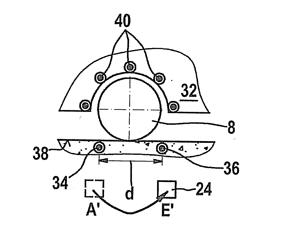
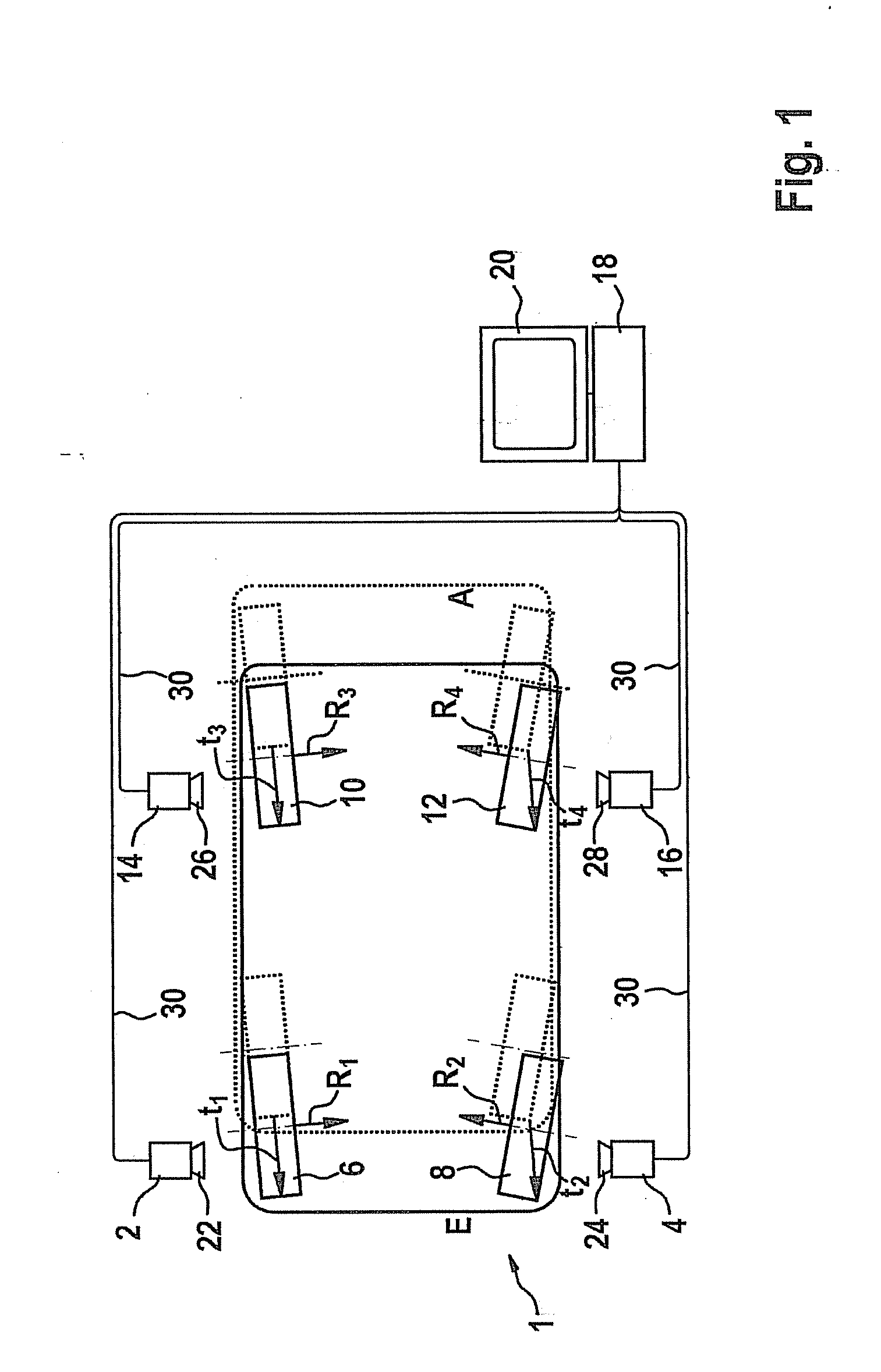
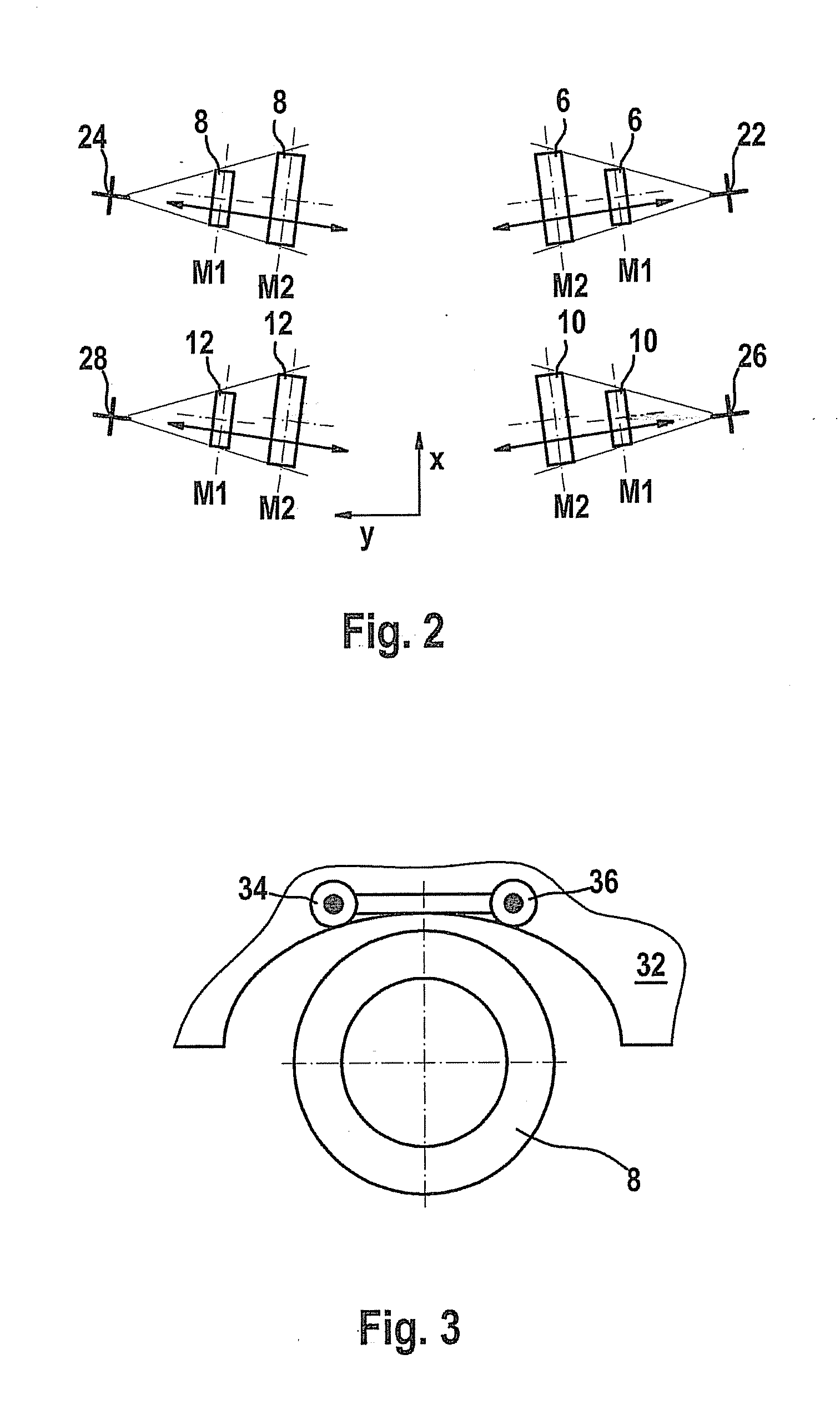
[0029]FIG. 1 shows the schematic representation of a device according to the present invention for measuring the wheel suspension geometry of a vehicle, from above.

[0030]The device has four measuring heads 2, 4, 14, 16, which are situated in each case pairwise opposite one another, on both sides of a vehicle 1. Measuring heads 2, 4, 14, 16, on their side facing vehicle 1, each have a monocular picture recording device 22, 24, 26, 28, which is designed as a camera, for example. The position of measuring heads 2, 4, 14, 16 in the coordinate system of the measuring location is known, and is not changed during the measurement.

[0031]Vehicle 1 has four wheels 6, 8, 10, 12, and is situated between measuring heads 2, 4, 14, 16 in such a way that in each case one of wheels 6, 8, 10, 12 is positioned in the field of view of one of picture recording devices 22, 24, 26, 28. Measuring heads 2, 4, 14, 16 are connected via data lines 30 to an evaluation device 18 for evaluating the data recorded a...


PUM


Abstract

In a method for wheel suspension alignment, the following steps are carried out: providing a wheel suspension alignment system having four measuring heads situated in a known position with respect to one another, of which each has a monocular picture recording device, the relative position of the measuring heads with respect to one another being known; recording in each case one wheel or a measuring target mounted on it in an initial position of the vehicle, using each of the four measuring heads; shifting the vehicle from the initial position to at least one further position; recording in each case one wheel, or a measuring target mounted on it, of the vehicle standing in the further position, using each of the four measuring heads; recording a reference target having a known pattern mounted on the vehicle, using one of the four measuring heads in at least one of the initial position and the further position of the vehicle, and determining from this an absolute scale for the measuring heads; carrying out local 3D reconstructions for determining the translation vectors, the rotation vectors and the wheel rotational angles between the at least two positions, as well as the wheel rotational centers and the wheel rotational axes of the wheels; and determining the wheel suspension alignment parameters of the vehicle, especially the camber, the single toe and / or the total toe, the wheelbase and the tread width.

Description

FIELD OF THE INVENTION[0001]The present invention relates to a method for wheel suspension measurement and a device for measuring the wheel suspension geometry of a vehicle.BACKGROUND INFORMATION[0002]A device for determining the wheel geometry and / or the axle geometry of motor vehicles is described in German Patent Application No. DE 107 57 763 and European Patent No. EP 1 042 643 B1, using an optical measuring device having at least two picture recording devices. In this instance, a so-called stereo measuring system is involved, having binocular (stereo) picture recording devices. Such binocular picture recording devices require much effort and are costly.[0003]In other wheel alignment systems, like one that is described, for example, in U.S. Pat. No. 6,134,792, measuring targets having passpoint networks are used, which have to be produced with high precision, and are therefore also costly. Furthermore, in an everyday repair shop environment, such high precision measuring targets...

Claims


Application Information

Patent Timeline
IPC IPC(8): G01M15/00
CPCG01B2210/143G01B11/2755
Inventor NOBIS, GUENTERABRAHAM, STEFFENUFFENKAMP, VOLKER
Owner BEISSBARTH
Learn More