
Fluid volume alarm system

Inactive Publication Date: 2011-12-15
LINSENMEYER TODD A +2
View PDF8 Cites 82 Cited by
  • Summary
  • Abstract
  • Description
  • Claims
  • Application Information

AI Technical Summary

Benefits of technology

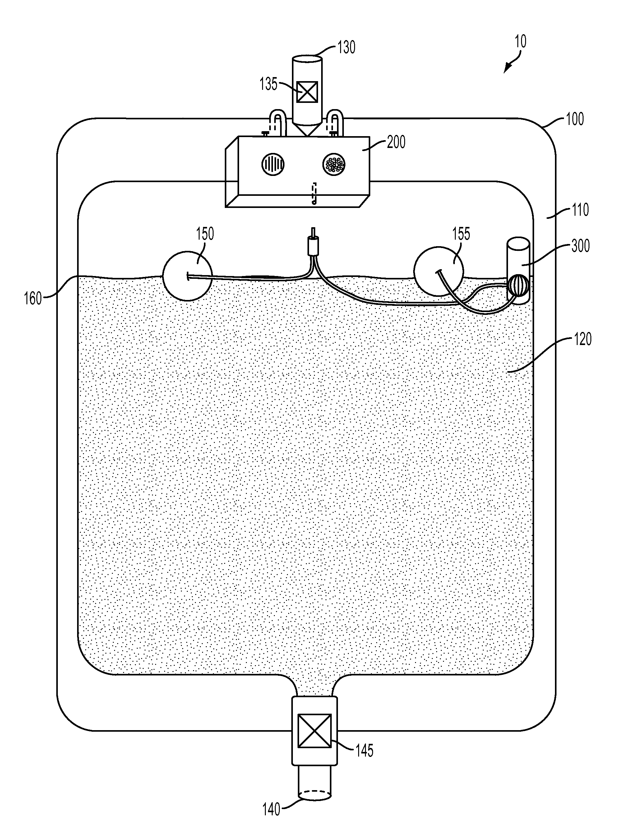
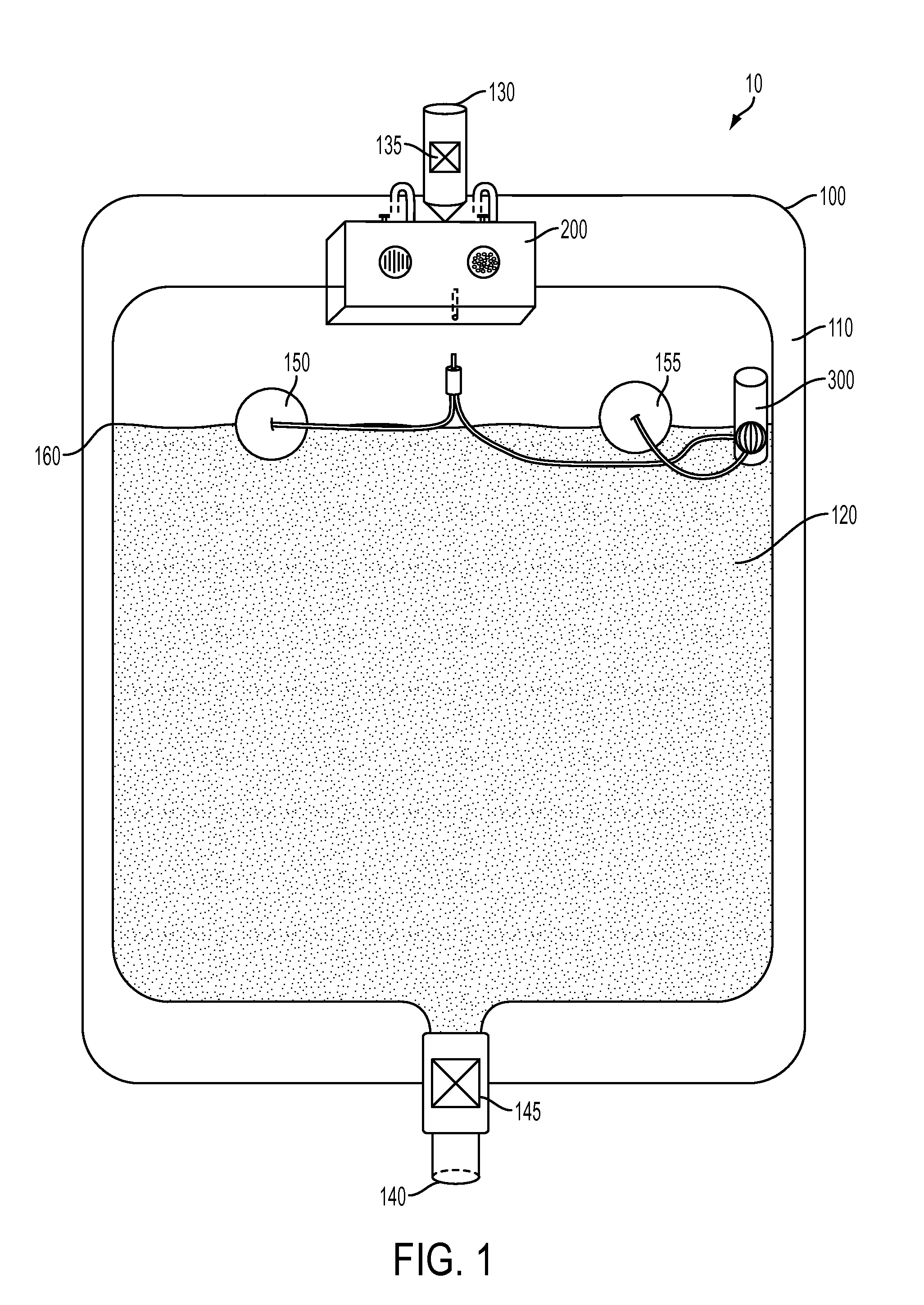
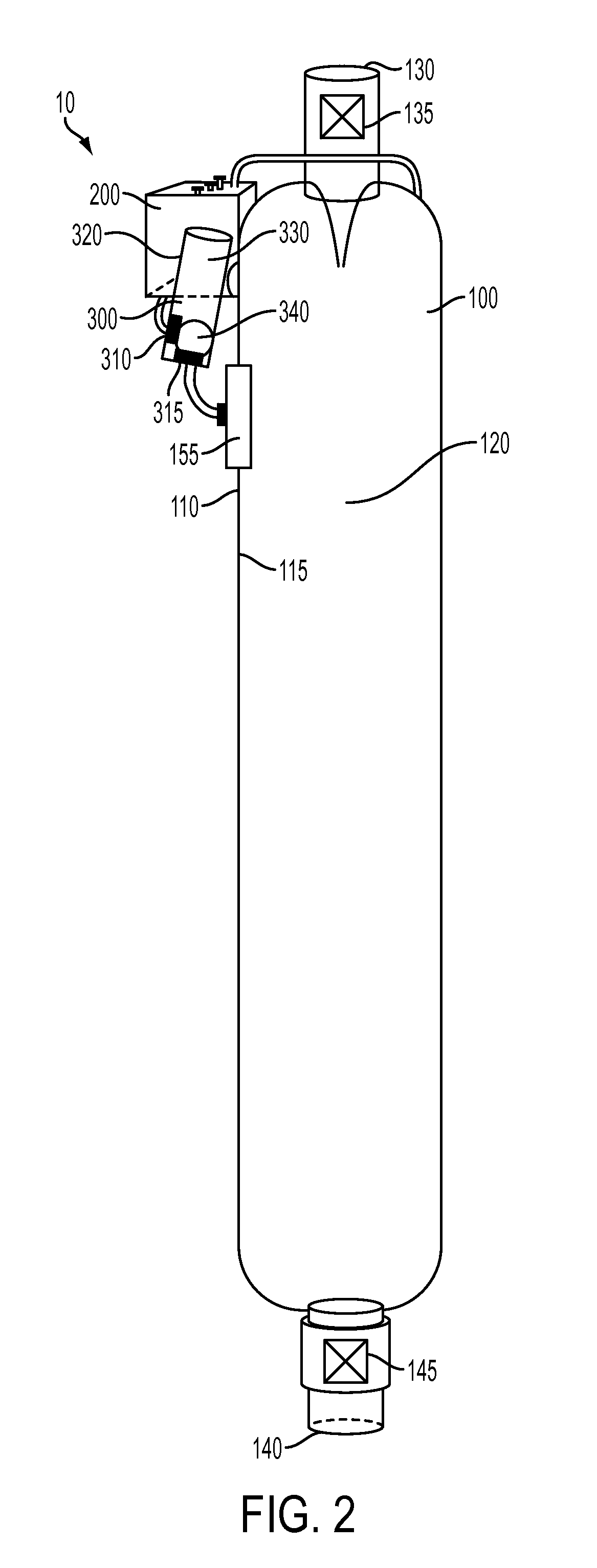
[0011]The system also comprises an alarm module coupled to a power supply. The alarm module comprises at least two terminals, each in electrical communication with one of the at least two electrodes. In use, in one aspect, when the fluid in the container reaches the predetermined fluid level, the fluid disposed within the interior volume of the container completes an electrical circuit between the at least two electrodes and the alarm module. This energizes the alarm and alerts the practitioner that the fluid has met or has exceeded the predetermined level.

Problems solved by technology

However, when a catheter is inserted, the bladder becomes colonized with bacteria within several days.
However if urine does not drain freely into the bag the bladder becomes over stretched.
Of even more concern is that an over stretched bladder can force the colonized bacteria to get into the bloodstream (bacteremia), causing fever and a severe infection.
Practitioners like to know the status of a fluid collection bag because, when a fluid collection bag becomes over-filled it will not allow any further drainage of urine into the fluid collection bag, resulting in back pressure and causing the bladder to get over distended.
If the urine collection bag becomes over-filled, it can cause the external condom catheter to fall off, causing significant embarrassment due to urine leakage.
First, the over-filled collecting bag may cause back up of urine into the tube and stretch up the condom, pulling it on the skin.
Second, the over-filled collection bag may get too heavy and pull the condom off the skin.
These blood clots can, then, obstruct the catheter, causing bladder over distention with the same problems discussed above.

Method used


Image

  • Fluid volume alarm system
  • Fluid volume alarm system
  • Fluid volume alarm system

Examples


Embodiment Construction

[0027]The present invention can be understood more readily by reference to the following detailed description, examples, drawing, and claims, and their previous and following description. However, before the present devices, systems, and / or methods are disclosed and described, it is to be understood that this invention is not limited to the specific devices, systems, and / or methods disclosed unless otherwise specified, as such can, of course, vary. It is also to be understood that the terminology used herein is for the purpose of describing particular aspects only and is not intended to be limiting.

[0028]The following description of the invention is provided as an enabling teaching of the invention in its best, currently known embodiment. To this end, those skilled in the relevant art will recognize and appreciate that many changes can be made to the various aspects of the invention described herein, while still obtaining the beneficial results of the present invention. It will also...


PUM


Abstract

A fluid volume alarm system is presented. The alarm system has a container for storing fluid, and alarm module coupled to the container for notifying a user or observer that the fluid within the container has reached a predetermined level. The container has at least one exterior wall and defines an interior volume for at least temporary storage of fluid. In one aspect, there are at least two electrodes disposed on an interior portion of the exterior wall of the container and positioned at a position thereon an interior portion of the exterior wall corresponding to a predetermined fluid level at which it is desirable to receive an alarm. The system also has an alarm module configured to alert the practitioner that the fluid has met or has exceeded the predetermined level.

Description

FIELD OF THE INVENTION[0001]Presented herein is a fluid volume alarm system. More specifically, presented herein is a fluid volume alarm system for providing an alarm when the level of fluid within a container surpasses or goes below a predetermined level.BACKGROUND OF THE INVENTION[0002]Often times, Indwelling catheters have widespread use for a number of medical conditions. They are used for those who are unable empty their bladders (urinary retention) or unable to hold back their urine (urinary incontinence). They may be passed into the bladder through the urethra or surgically placed into the bladder from a suprapubic location. Indwelling catheters are also used to monitor urine output, typically for post-surgical or acutely ill hospitalized patients, or to drain the bladders of patients who are unconscious. The catheter is attached to a fluid collection bag.[0003]However, when a catheter is inserted, the bladder becomes colonized with bacteria within several days. Careful drain...

Claims


Application Information

Patent Timeline
IPC IPC(8): G08B21/00
CPCG01F23/242G01F23/241G08B21/182
Inventor LINSENMEYER, TODD A.DITROLIO, JOSEPH V.LINSENMEYER, DOROTHY F.
Owner LINSENMEYER TODD A
Learn More