
Adjustable brace

a brace and adjustable technology, applied in the field of adjustable braces, can solve the problems of not being able to adjust the size of the cast to compensate for the reduced size, and achieve the effects of reducing weight, improving comfort and hygiene, and simplifying the design and construction of the bra

Inactive Publication Date: 2011-12-08
3D SYST INC
View PDF1 Cites 26 Cited by
  • Summary
  • Abstract
  • Description
  • Claims
  • Application Information

AI Technical Summary

Benefits of technology

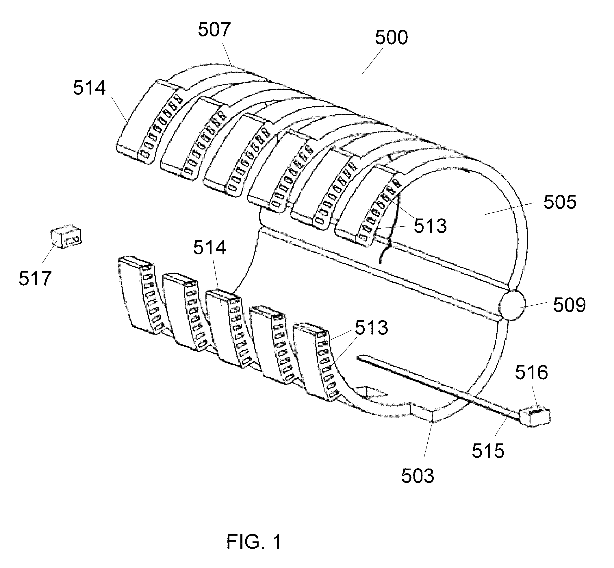
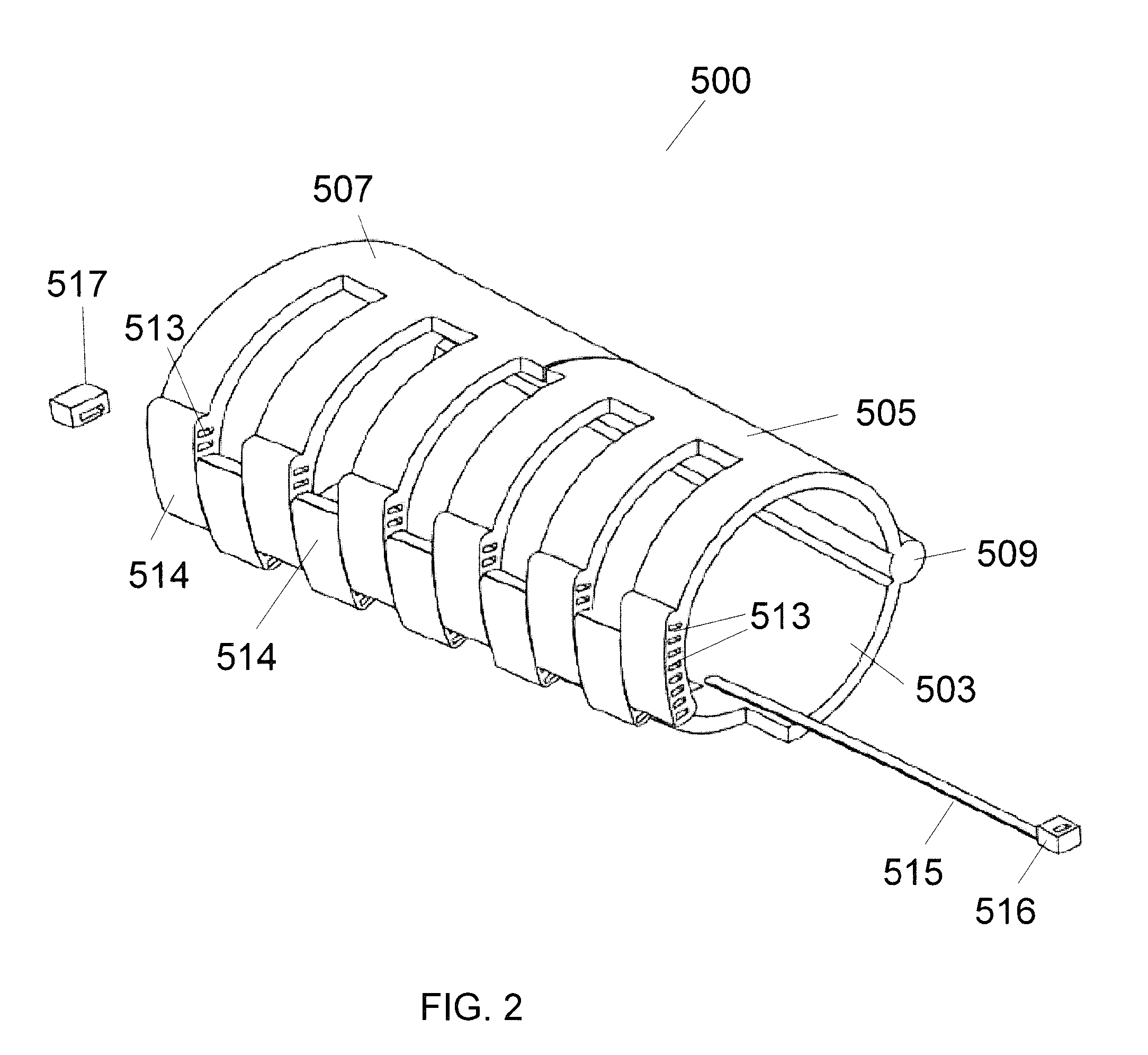
[0006]The adjustable brace can have various different configurations. In an embodiment, the first section can be coupled to the adjustable sections along one edge with a plurality of hinges and a plurality of adjustable fasteners on the opposite edge. As the surface of the patient changes, the corresponding adjustable section can be moved by rotating the adjustable section about the hinge. The adjustable fasteners can include a locking mechanism that allows the adjustable sections to be set at a specific cross section size and prevents the cross section from expanding or compression. When the adjustable section is at the proper position, the adjustable fastener can be locked. The brace can be adjusted as many times as necessary to help the patient recover.
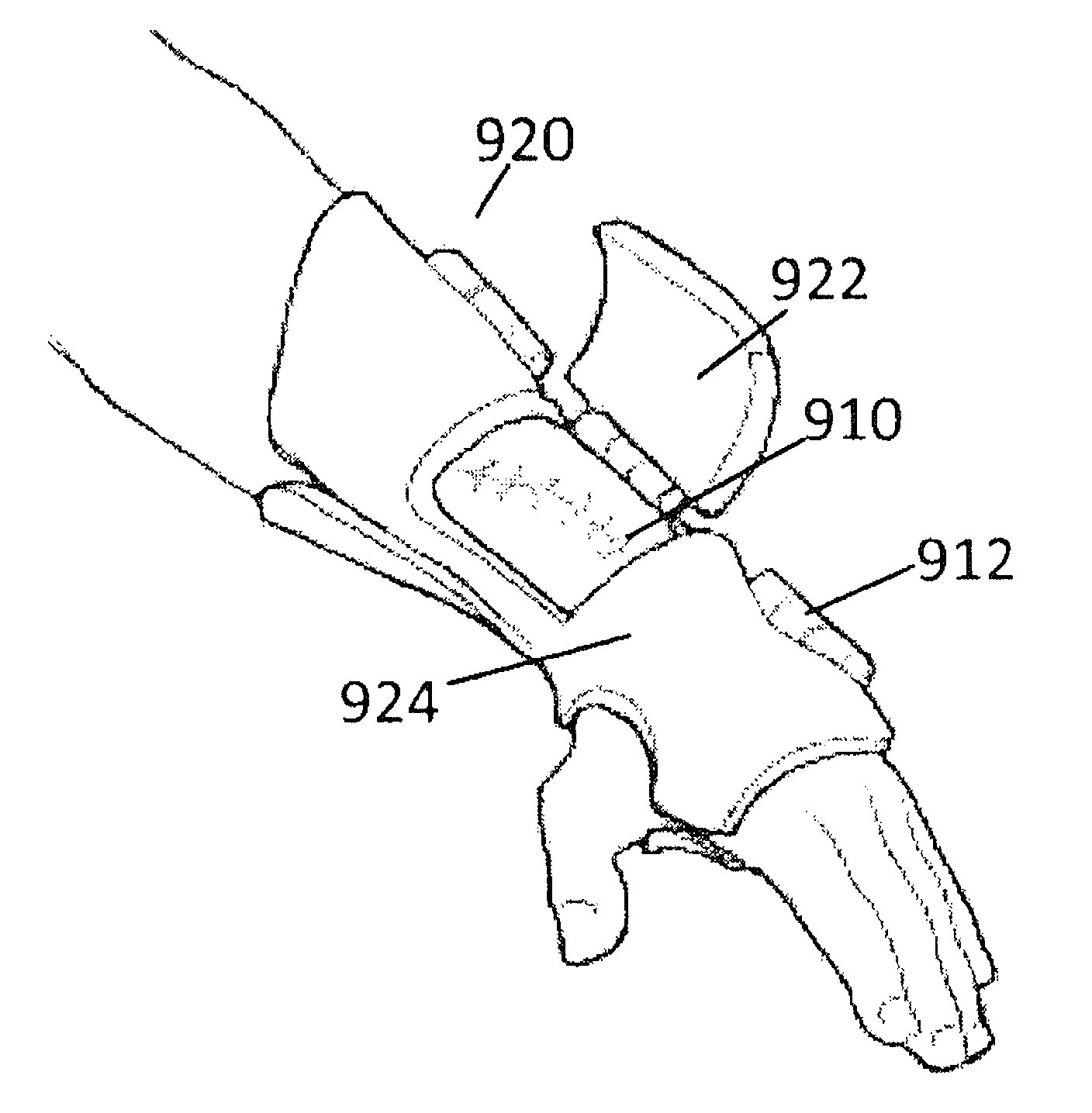
[0010]In yet another embodiment, a brace or cast can be designed having a plurality of accessible regions. Each region can be attached to a hinge or other releasable fastener that allows the portion of the brace for access to the patient. This can be designed over a specific area of interest, for example a wound area that needs to be cleaned or periodically checked and then protected again. By placing a number of these accessible regions adjacent to each other, the body can be cleaned by opening each region individually while the rest of the body is held within the device. The inventive brace allows improved comfort and hygiene while still protecting the patient during the healing process. For example, medical procedures may require placing pins or other objects in a patient. It may be necessary to avoid contact with and allow inspection of these areas. By using an access region over these areas, the doctor will be able to inspect the area to insure that the patient is healing properly. The accessible region feature can also be particularly useful for infants who will need to be cleaned regularly. The inventive brace can be designed with access to the lower torso regions that allow the child to be cleaned. The region can be opened for cleaning and then closed after cleaning is completed. This design is a significant improvement over casts that must be partially sawed to access the child for cleaning.
[0011]In an embodiment, the brace or cast has a smooth inner surface that conforms to the scanned surface of the limb. Because the inner surface of the brace accurately conforms to the patient, the brace can be worn by the patient without any padding. The brace can be made of a hard plastic material and the inner surface of the brace should also be very smooth. In order to comfortable, the inner surface can have a surface finish of less than of less than 500 Ra μ inch. A brace or case that can be worn by a patient without padding has several benefits including: simplified brace design and construction, less weight, lower profile, better ventilation, no absorption of water, easier cleaning, etc.

Problems solved by technology

A problem with rigid casts is that they are not adjustable in size.
When these changes occur, the cast cannot be adjusted to compensate for this reduced size.

Method used


Image

  • Adjustable brace
  • Adjustable brace
  • Adjustable brace

Examples


Embodiment Construction

[0025]The present invention is a custom designed and adjustable cast or brace having a interior surfaces that corresponds closely to a body. When a patient injures a limb, such as a broken bone, there can be a swollen area around the injury. The adjustable brace can be designed to closely fit around the limb when it is initially injured. As the injured limb heals, the swelling can go down which results in an open volume between the limb and the cast or brace. This open volume reduces the support for the bone and the limb. When an open space is detected, the adjustable brace can adjusted to reduce the cross section of the brace at the region that surrounds the portion or portions of the limb that are now smaller in size. Thus, the adjustable brace can be adjusted to accurately fit the patient's anatomy as the surface changes.

[0026]With reference to FIG. 1, an embodiment of an adjustable brace 500 is illustrated having a first lower portion 503 and a first upper adjustable portion 505...


PUM


Abstract

An adjustable brace includes a first portion for supporting one surface of a patient and a plurality of adjustable portions that allow the internal cross section of the brace to be adjusted. When a limb is injured, a patient may have a swollen limb and the adjustable brace can be set to a large cross section. As the limb heals, the swelling decreases and the limb cross section also decreases due to atrophy. The adjustable couplings are adjusted to reduce the cross section to properly fit the limb of the patient and provide proper protection and support during the healing process.

Description

CROSS REFERENCE TO RELATED APPLICATIONS[0001]This application is a continuation-in-part of U.S. patent application Ser. No. 12 / 820,968, “Modular Custom Braces, Casts And Devices And Methods For Designing And Fabricating filed Jun. 22, 2010 which is a continuation-in-part of U.S. patent application Ser. No. 12 / 615,196, now U.S. Pat. No. 8,005,651, “Custom Braces, Casts and Devices And Methods For Designing And Fabricating” filed Nov. 9, 2009 which claims priority to U.S. Provisional Patent Application No. 61 / 112,751, “Brace And Cast” filed on Nov. 9, 2008, U.S. Provisional Patent Application No. 61 / 168,183, “Orthopedic Braces” filed in Apr. 9, 2009, and U.S. Provisional Patent Application No. 61 / 185,781, “Bespoke Fracture Brace” filed in Jun. 10, 2009. This application also claims priority to U.S. Provisional Patent Application No. 61 / 375,699, “Adjustable Brace” filed Aug. 20, 2010. The contents of U.S. patent application Ser. Nos. 12 / 820,968, 12 / 615,196, 61 / 375,699, 61 / 112,751, 61 / 1...

Claims


Application Information

Patent Timeline
Patent Type & Authority Applications(United States)
IPC IPC(8): A61F5/00
CPCA61F5/01A61F5/02A61F5/013A61F5/0123A61F5/0102A61F2005/0132
Inventor SUMMIT, SCOTTTRAUNER, KENNETH B.
Owner 3D SYST INC
Learn More