
Rolling projectile with extending and retracting canards

a projectile and canard technology, applied in direction controllers, instruments, weapons, etc., can solve the problems of not being practical for many projectiles, reducing weight and space requirements, and affecting the performance of maneuvering, etc., and achieves the effect of being less expensive and simpl

Inactive Publication Date: 2011-12-08
NOSTROMO HLDG LLC
View PDF24 Cites 20 Cited by
  • Summary
  • Abstract
  • Description
  • Claims
  • Application Information

AI Technical Summary

Benefits of technology

"The invention is a system for controlling missiles or projectiles that is simpler and less expensive than previous systems. It includes a rolling projectile with extending and retracting canards that can be extended and retracted at predetermined frequencies to correct the path of the projectile. The system also includes a flight control computer and an interface to the fuze and projectile body. The steering system is fixed to the projectile body and uses GPS or INS navigational technology to measure the projectile's position and initiate the flight control actuators that precisely extend and retract the canards. The canards extend and retract for times and at predetermined frequencies to provide low g correction of the projectile's path. The system provides a cost-effective solution for smart weapons and can be easily installed and programmed."

Problems solved by technology

In this fashion a single pair of control surfaces can do the work of two pairs of control surfaces, reducing weight and space requirements with some penalty in maneuver performance.
However, the dithering canard scheme needs to be packed and then deployed after launch, which usually makes the mechanical design complex.
However, this system is quite complex and not practical for many projectiles.
Similar to the control system discussed above, this system is much more complex than is needed for slow rolling projectiles.

Method used


Image

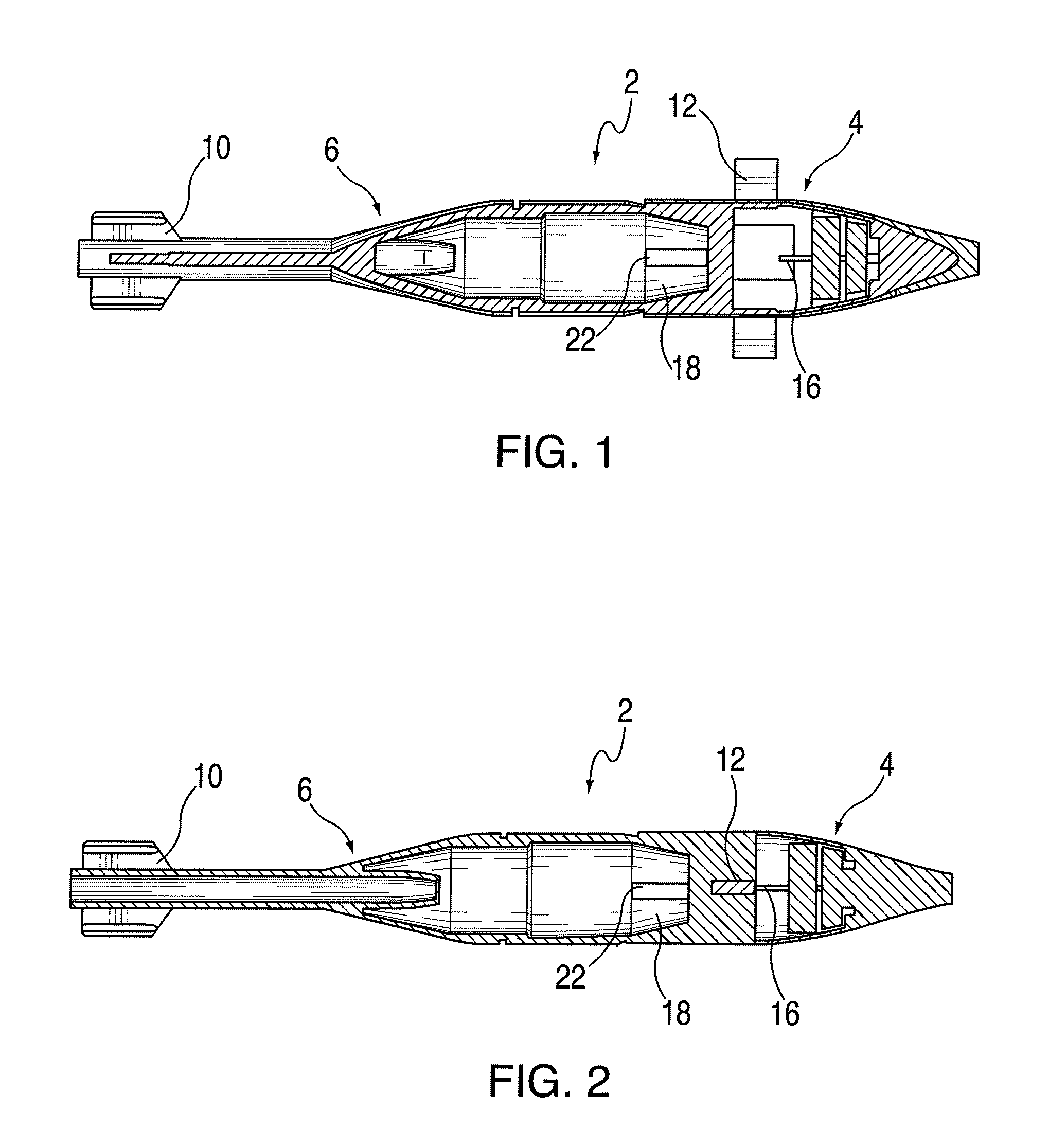
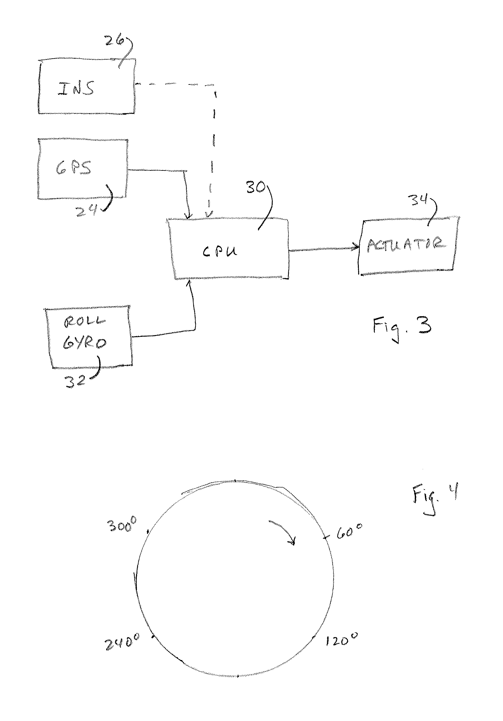
  • Rolling projectile with extending and retracting canards
  • Rolling projectile with extending and retracting canards
  • Rolling projectile with extending and retracting canards

Examples


example

[0070]In a calculated example of an embodiment of the invention, a mortar with a mass of 4.40 kg was fired at an initial angle of 45° with a velocity of 300.00 m / sec. The rotational frequency was 8.00 Hz, at the maximum lateral acceleration.

[0071]The time of the flight was 36.40 sec, the range being 5506.0 m. The maximum height was 1640.30 m, at which point the velocity of the projectile was at a minimum of 147.24 m / sec. This occurred 19.50 sec after launch. The velocity at impact was 194.76 m / sec, at an angle of 54.73°. The maximum lateral correction was calculated at 233.69 m.

[0072]FIG. 6 is a graph that represents the height of the path of the projectile from launch to impact, without canards extended. FIG. 7 is a graph that represents the amount of lateral correction necessary. FIG. 8 is a 3-dimensional representation that represents the uncorrected path 54 of the projectile as compared to a corrected path 56 with corrections according to the invention.


PUM


Abstract

A slow rolling projectile comprises a projectile body has a forward section and a rear section and having a longitudinal axis. Two or more canards in the forward section are capable of being extended from and retracted into the projectile body at predetermined frequencies and / or for predetermined times. Two or more tail fins in the rear section are fixed coextensive to or at an angle to the longitudinal axis, and an actuator extends and retracts the canards. The canards are capable of being extended and retracted at a rate based on the rotation of the projectile sufficient to correct for lateral movement. A GPS or INS navigational system activates an actuator to extend and retract the canards.

Description

CROSS-REFERENCE TO RELATED APPLICATION[0001]This application is based upon and claims the priority of co-pending and commonly assigned U.S. Provisional Patent Application Ser. No. 61 / 254,840, filed Oct. 26, 2009, incorporated herein in its entirety by reference.FIELD OF THE INVENTION[0002]This invention is directed to a system for controlling missiles or projectiles, where canards extend and retract at predetermined frequencies.BACKGROUND OF THE INVENTION[0003]In the field of guided weapons there are primarily two possible aerodynamically controlled airframes, namely, a rolling airframe and a roll stabilized airframe. These two schemes cover most of the missiles and projectiles with aerodynamic controls.[0004]A missile or projectile with a rolling airframe has an airframe that is free to roll or its rolling motion is controlled by a device (such as a rolleron) to keep the roll rate at a certain value. Aerodynamic controlled deflections can then be coordinated with the roll position,...

Claims


Application Information

Patent Timeline
Patent Type & Authority Applications(United States)
IPC IPC(8): F42B10/00F42B15/01
CPCF42B10/14F42B15/01F42B10/64F42B10/00F42B10/42F42B10/46
Inventor MARTINEZ, MARCELO EDGARDO
Owner NOSTROMO HLDG LLC
Learn More