
Anti-extraction safety device for a guidance set comprising two inclined rollers rolling on a rail

Inactive Publication Date: 2010-03-25
LOHR IND
View PDF6 Cites 8 Cited by
  • Summary
  • Abstract
  • Description
  • Claims
  • Application Information

AI Technical Summary

Benefits of technology

[0023]Indeed, with the device of the prior art, the flanges turn along with the guide rollers when the vehicle moves forward. When these flanges encounter an object inside the groove that runs alongside the rail, their rotation encourages the rollers to rise up on the rail by pressing on this object and the dynamic force that keeps the guide assembly from being pulled out is greatly decreased.
[0026]With the safety device of the invention, the pull-out force no longer passes through the bearings. As a result, they can be simpler and less expensive, e.g., simple ball bearings.
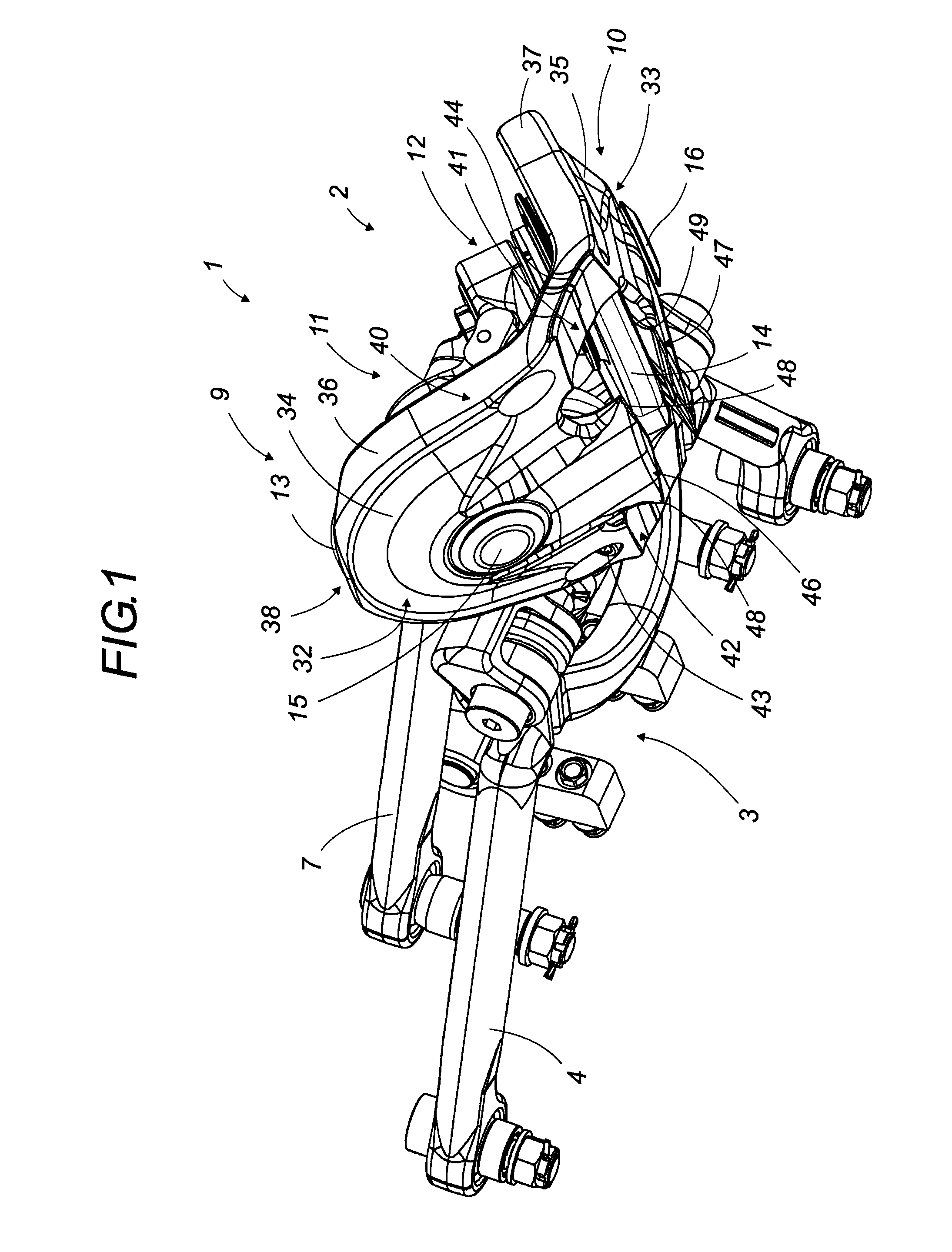
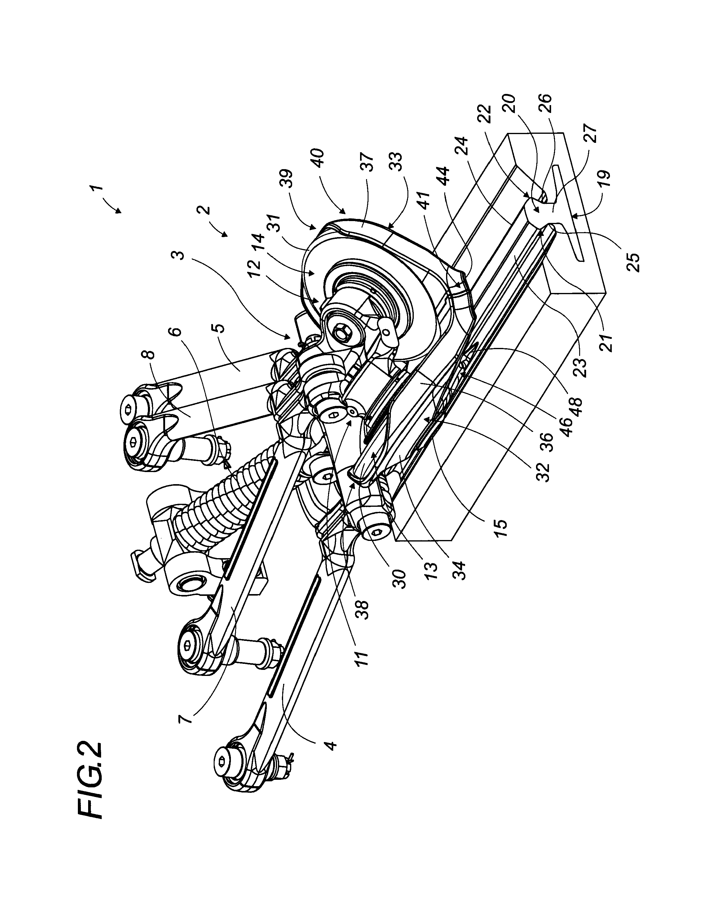
[0028]The shroud elements preferably have an enveloping shape that covers the outer faces of the guide rollers and, if desired, a part of their peripheral edge. In addition to their anti-extraction function, they may thus protect the rollers from objects that are projected and ejected while they are rolling.
[0032]It is advantageously possible to connect the shroud elements in an area situated near the rail in order to reinforce the resistance against spacing of their extensions. The pull-out resistance is greatly improved by doing this, because given the inclination of the faces resting on the rail, in order to improve pull-out resistance, one must—among other things—improve the spacing resistance of these extensions.
[0033]Additionally, it is possible to thicken these extensions locally in all available areas without involving the gauge of the rail grooves. These reinforcements also make it possible to improve the lateral flexion resistance of the extensions.

Problems solved by technology

The guide rollers are pulled pull away from the guide rail, which possibly results in derailment.
Indeed, because of exposure to bad weather and to the ambient environment of the guide track, it is common for the guide rail and / or its side grooves to be locally cluttered and / or obstructed with debris of all kinds—plants, ice, snow, rocks or other bodies or foreign objects left by accident or deliberately—that may constitute an obstacle for the guide rollers, causing them to be lifted up and off of the rail.
The lifting of the guide rollers and the extraction of the guide assembly out of the guide area of the rail represent unacceptable risks resulting in major problems, particularly the derailment of the guide assembly and subsequently of the vehicle.

Method used


Image

  • Anti-extraction safety device for a guidance set comprising two inclined rollers rolling on a rail
  • Anti-extraction safety device for a guidance set comprising two inclined rollers rolling on a rail
  • Anti-extraction safety device for a guidance set comprising two inclined rollers rolling on a rail

Examples


Embodiment Construction

[0043]The anti-extraction safety device of the invention will now be described in detail with reference to FIGS. 1 to 8. Equivalent parts shown in the various figures will have the same reference numbers.

[0044]In the remainder of this description, the concepts of up, down, lower and upper, etc. will be defined based on the orientation used in the various figures.

[0045]Likewise, front and rear will be defined based on the vehicle's direction of travel.

[0046]The safety device of the invention applies more specifically to a guide assembly 1 as shown in the figures.

[0047]It is composed of a guide head 2, mounted in an articulated fashion onto a swiveling support 3, which is borne by the vehicle via two swiveling arms 4 and 5 and an elastic connection 6, e.g., a spring. This moving element carries the guide head 2 like a gimbal joint using several swivel joints, as well as a restoring means carried out by two articulated arms 7 and 8.

[0048]Of course, this mechanical bearing and articulat...


PUM


Abstract

An anti-extraction safety device having, for each roller (13, 14), a rotationally fixed, preferably enveloping, shroud element (32, 33) forming a single-component functional mechanical set with its counterpart. The shroud parts are inclined and each has an extension (46, 47), at the base, which extends beneath the projecting flanks (21, 22) of the head of the guiding rail (19) to prevent extraction of the guidance set. At the front, the base of the shroud parts is preferably moulded into a spout for collecting and disposing of objects which may be present on the guiding track. The anti-extraction safety device can be used for rail guidance of road vehicles used for public transport.

Description

[0001]This application is a National Stage completion of PCT / FR2007 / 002047 filed Dec. 12, 2007, which claims priority from French patent application Ser. No. 06-11296 filed Dec. 22, 2006.FIELD OF THE INVENTION[0002]This invention relates to an anti-extraction safety device for a guide assembly of a road vehicle guided by two inclined rollers rolling on a rail.[0003]Advantageously, the safety device of the invention may also perform the function of removing objects that may be located on the guide track and that may interfere with the guiding of the vehicle.[0004]The invention applies more specifically, but not exclusively, to urban public transport vehicles that are guided along a guide rail by means of a guide assembly comprising two guide rollers inclined to form a V shape.BACKGROUND OF THE INVENTION[0005]To ensure their guidance, guided urban public transport vehicles of this type have a guide assembly that permanently follows a continuous guide rail along the vehicle's entire ro...

Claims


Application Information

Patent Timeline
IPC IPC(8): B61F9/00
CPCB62D1/265B61F9/00B62D1/26
Inventor ANDRE, JEAN-LUCLAMANNA, FRANCK
Owner LOHR IND
Learn More