
Universal hole cutter

Active Publication Date: 2011-12-08
ZHANG YINGEN
View PDF4 Cites 3 Cited by
  • Summary
  • Abstract
  • Description
  • Claims
  • Application Information

AI Technical Summary

Benefits of technology

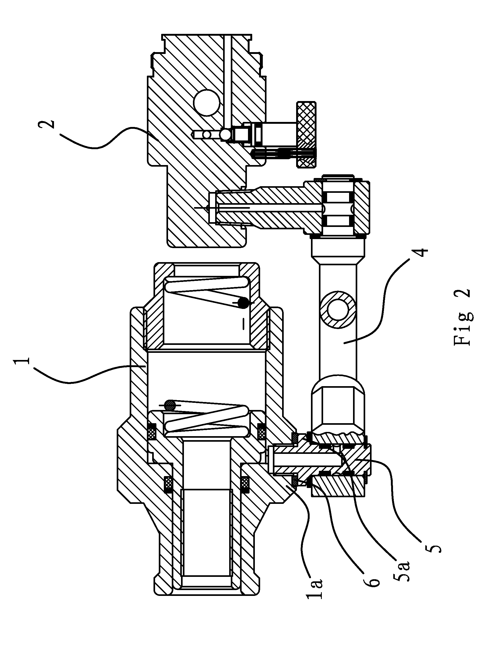
[0017]The connection piece has such a relatively large thickness that the surface of the connecting site of the pipe joint and the connection piece is enlarged, thereby improving the reliability of the connection between the pipe joint and the connection piece of the oil cylinder.
[0031]In addition, the oil path on the oil cylinder is implemented to be a straight hole which tends not to have a blocking defect and thereby improves the reliability of the complete hole cutter in use. Further, the oil cylinder made from aluminum alloys or magnesium alloys has a small weight, and the complete hole cutter could be conveniently used.

Problems solved by technology

Therefore, the applicability of said hold cutters is relatively poor in different occasions of use.
However, the hose could not directly support the cylinder, which brings a problem of supporting the cylinder during use.
In this regard, such a hydraulic hole cutter could not be conveniently used.
In addition, the hose has such a limited strength that it tends to be detached or broken due to hauling during moving processes.
In this case, the oil cylinder has a large weight and thus could not be conveniently used.
According to such a configuration, the oil path tends to be blocked, and the welding site of the oil inlet bolt and the oil cylinder does not have an aesthetic appearance.

Method used


Image

  • Universal hole cutter
  • Universal hole cutter
  • Universal hole cutter

Examples


Embodiment Construction

[0038]Embodiments of the present invention will be described in detail below with reference to the drawings, where like reference numerals indicate identical or functionally similar elements.

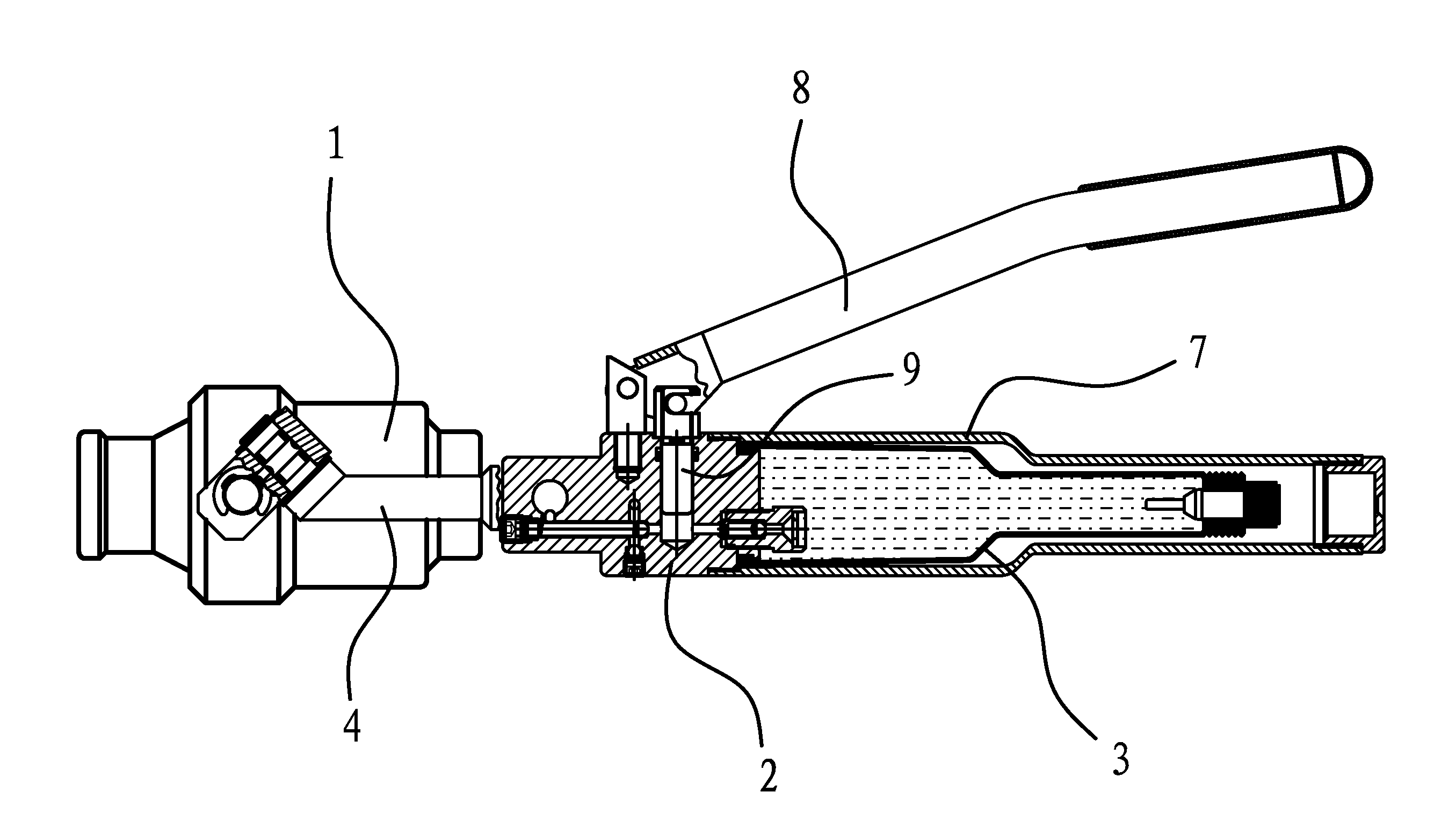
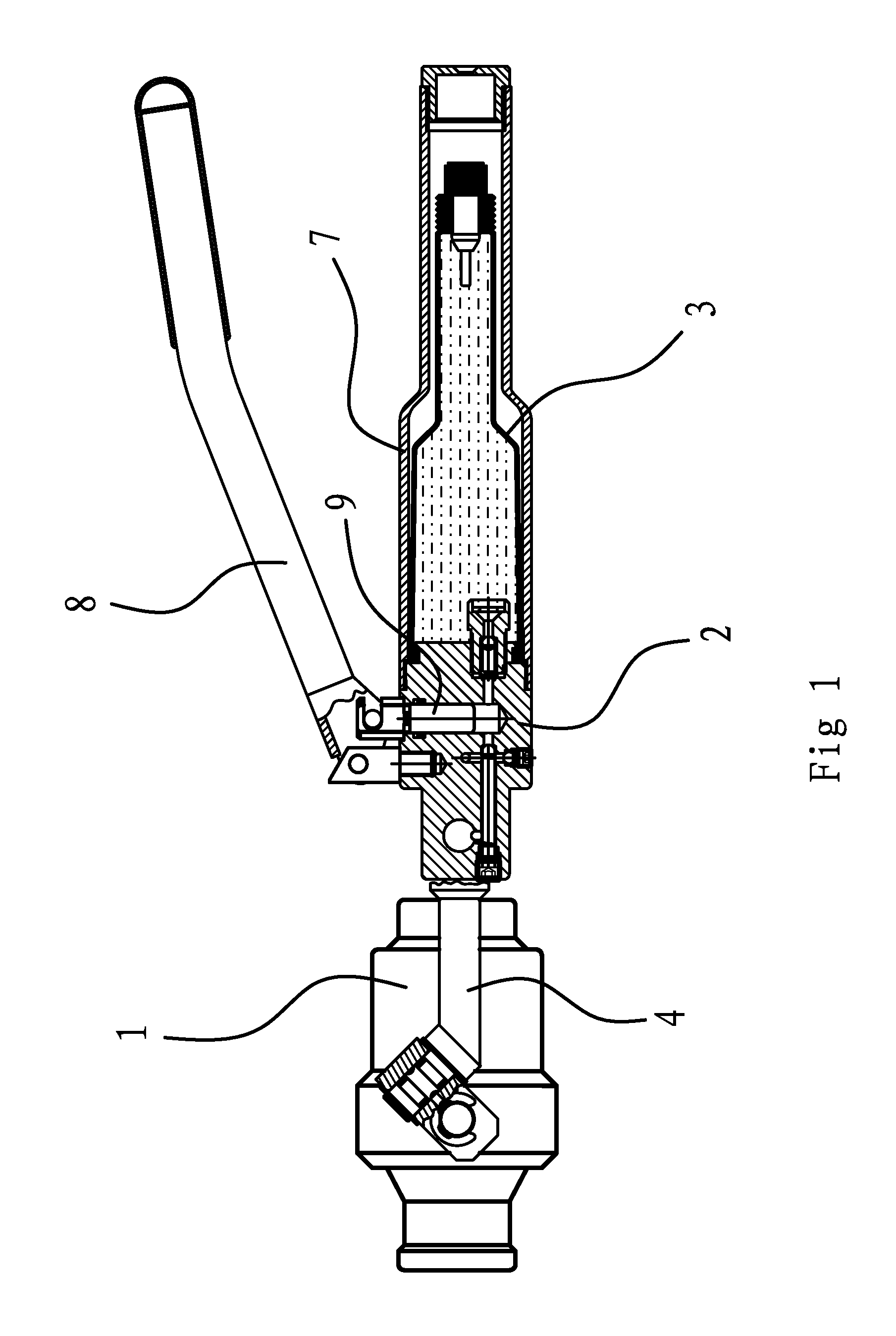
[0039]As shown in FIGS. 1 and 2, the universal hole cutter includes an oil pump body 2, an oil cylinder 1 and an oil storage chamber 3. The oil pump body 2 is fixedly connected to the oil storage chamber 3, and the oil path between the oil pump body 2 and the oil storage chamber 3 is in communication. A pressure mechanism is provided on the oil pump body 2 for pressing the power oil within the oil storage chamber 3 into the oil cylinder 1.

[0040]The pressure mechanism includes a movable handle 8 and a stationary handle 7. The movable handle 8 is hinged to the oil pump body 2, and the stationary handle 7 is fixedly connected with the oil pump body 2. A plunger 9 is connected to the movable handle 8. The plunger 9 is inserted into a plunger hole of the oil pump body 2. The plunger hole is communica...


PUM


Abstract

The present invention discloses a universal hole cutter in the field of mechanics, comprising an oil pump body, an oil cylinder and an oil storage chamber, in which the oil pump body could be fixedly connected with the oil storage chamber and the oil paths thereof could be communicated with each other. A pressure mechanism could be provided on the oil pump body for pressing the power oil within the oil storage chamber into the oil cylinder. The oil cylinder could be fixedly threaded with a pipe joint communicating with the internal cavity of the oil cylinder, and the pipe joint could be communicated with the oil pump body through a rigid movable linkage mechanism which could rotate the oil cylinder with respect to the oil pump body. Compared to the prior art, in the universal hole cutter thus described, the thread connection of the pipe joint and the oil cylinder is reliable and convenient. Furthermore, no welding site exists between the pipe joint and the oil cylinder, which makes a tidy connection and an aesthetic appearance of the complete hole cutter. The universal hole cutter tends not to have a blocking defect and has a good reliability in use.

Description

BACKGROUND OF THE INVENTION[0001]1. Field of Invention[0002]The present invention relates to a hole cutter for making holes in a metal sheet, in particular, to a universal hole cutter in the field of mechanics.[0003]2. Related Art[0004]In order for making holes in a workpiece or metal sheet, people have designed various kinds of hydraulic hole cutters. The existing hole cutters are generally consisted of a oil cylinder and a oil pump body in which the oil cylinder is directly fixed to the oil pump body. In these hole cutters, the oil cylinder could not rotate with respect to the oil pump body, so the oil pump body has to be move together when the position of the oil cylinder is to be changed. Therefore, the applicability of said hold cutters is relatively poor in different occasions of use.[0005]To address the afore-mentioned problems, someone has designed a hole cutter in which the oil cylinder could move with respect to the oil pump body. For example, a hydraulic hole cutter is di...

Claims


Application Information

Patent Timeline
IPC IPC(8): F16K21/00
CPCB21D28/24B21D28/002Y10T137/3331B21D28/343
Inventor ZHANG, YINGEN
Owner ZHANG YINGEN
Learn More