
Method and apparatus for measuring the density of a flowing fluid in a conduit using differential pressure

Inactive Publication Date: 2011-12-08
MOORE BARRY +1
View PDF13 Cites 18 Cited by
  • Summary
  • Abstract
  • Description
  • Claims
  • Application Information

AI Technical Summary

Benefits of technology

[0026]One of the many advantages to the technology set forth herein is that since the pressure drop measurements occur in overlapping areas of piping which, eliminates elbow effects ,there is a single assessment zone. this allows the arrangement to be considerably more compact and therefore more practical than the devices requiring velocity profile cancelling sections in advance of the pressure taps. This is particularly significant when applying this principal to larger diameter piping systems.
[0027]Owing to the fact that identical pipe runs are used upstream of the measurement sections and the pressure tap is perpendicular to the plane of the upstream elbow, the need for long and straight pipe runs is avoided and static pressure can be derived since the velocity profile effects are identical in symmetrical piping configurations and can therefore be cancelled out to derive a static pressure. The apparatus can operate in either an inverted or upright square wave configuration and one of the main principals of the device is to present symmetrical piping configurations upstream and downstream of both pressure taps connected to each differential pressure transducer. This therefore creates the need for a straight horizontal section at the top of the square wave between two symmetrical elbows thus it is a square U. This is a point of distinction relative to the prior art. In the prior art, a continuous or long radius bend between the top two pressure taps which defeats the symmetry and thus the velocity profile effects cannot be cancelled out close to the bend.

Problems solved by technology

The apparatus includes other processors and is thus somewhat complex.

Method used


Image

  • Method and apparatus for measuring the density of a flowing fluid in a conduit using differential pressure
  • Method and apparatus for measuring the density of a flowing fluid in a conduit using differential pressure
  • Method and apparatus for measuring the density of a flowing fluid in a conduit using differential pressure

Examples


Embodiment Construction

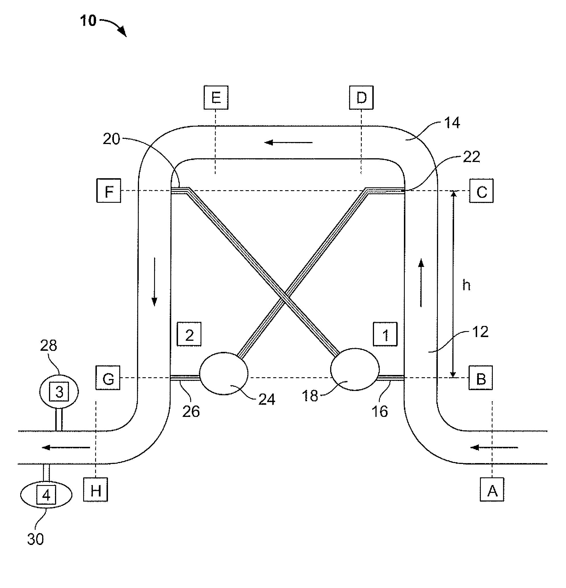
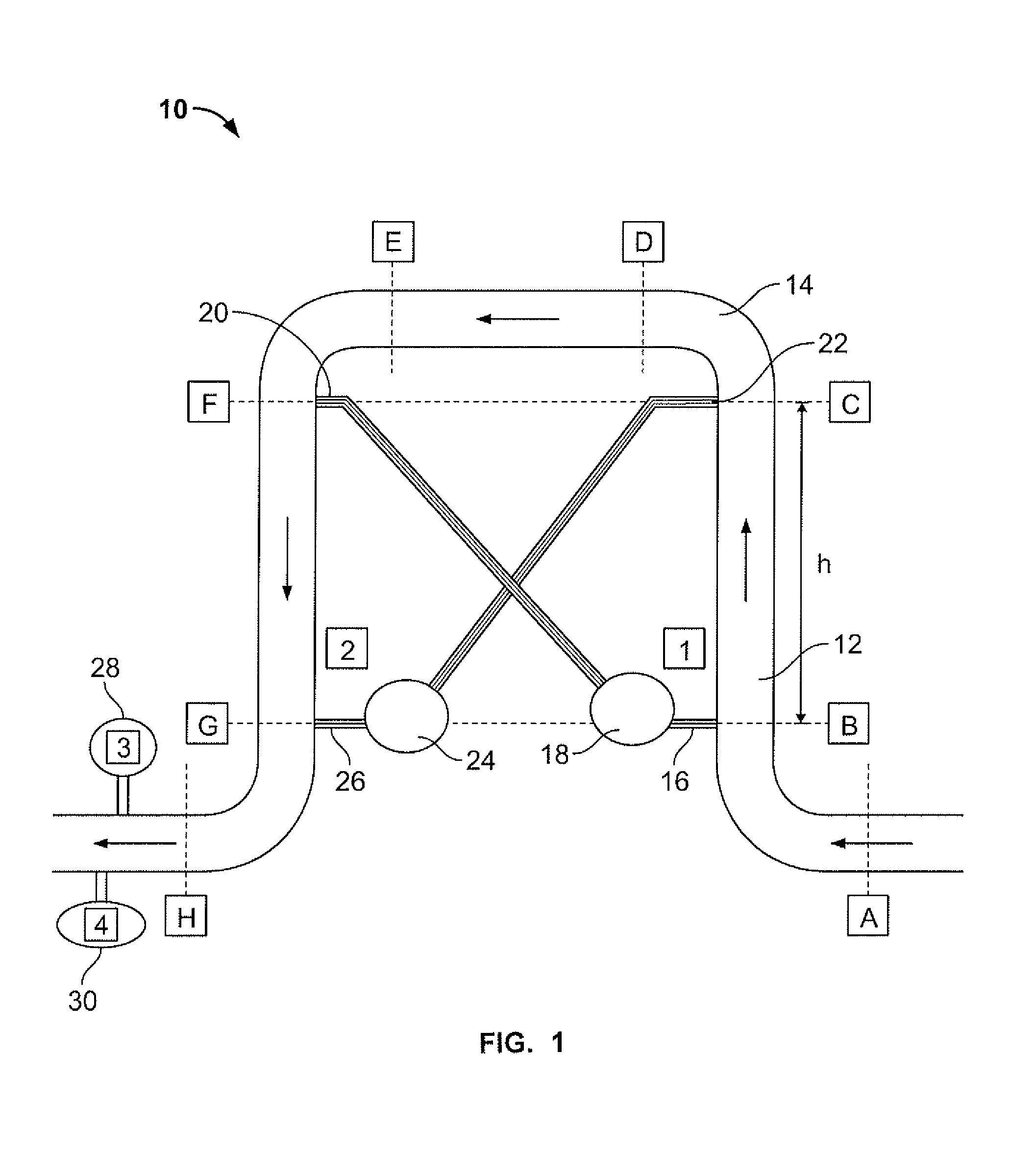
[0036]Referring initially to FIG. 1, shown is an example of the apparatus for effecting the measurements. The apparatus is generally denoted by numeral 10 and comprises a conduit 12 having a square wave profile, shown in the example as an inverted U shaped bend 14 and straight section DE.

[0037]In FIG. 1, the fluid enters the device at point A. A high pressure tap 16 for a transmitter 18 (TX1) is located immediately downstream of the elbow All The low pressure tap 20 for transmitter 18 is located immediately downstream of elbow EF at point F which is symmetrically located to the pressure tap at point B at elbow AR The pressure taps 16 and 20 are oriented symmetrically consequently any velocity profile effect is cancelled out.

[0038]The high pressure tap 22 for a second transmitter 24 (TX2) is located at point C at the inlet to elbow CD and with straight pipe AB upstream of C. The low pressure tap 26 for transmitter 24 is located at the inlet to elbow GH and with straight pipe FG upstr...


PUM


Abstract

A method and apparatus for determining the specific gravity of a monophasic or polyphasic fluid flowing in a conduit. The apparatus employs an square wave shaped tube known for its effectiveness in differential pressure measurements. The apparatus is configured such that the differential pressure is measured in crosswise manner Pressure taps comprising high and low pressure taps for a respective pressure sensing device are associated with a different leg. The apparatus has also been found to be effective for determining flow rate of the fluid in the conduit using differential pressure measurements.

Description

TECHNICAL FIELD[0001]The present invention relates to a method for measuring a fluid flowing in a conduit and more particularly, the present invention relates to a method of such measurement using differential pressure.BACKGROUND OF THE INVENTION[0002]A number of arrangements have been developed to measure fluid properties. As an example, in U.S. Pat. No. 2,768,529, dated Oct. 30, 1956, there is shown an inverted U tube with two differential pressure devices with one mounted on each arm of the U. The patent also provides the complete mathematical analysis showing the elimination of the friction effect. This reference establishes the straight arm art for measuring specific gravity as early as 1956.[0003]In U.S. Pat. No. 6,550,327 issued to Van Berk, Apr. 22, 2003, there is disclosed a device for measuring the density of a flowing medium.[0004]The device includes a pipe section in loop form having two arms which make an angle with the horizontal, which arms each contain two pressure s...

Claims


Application Information

Patent Timeline
IPC IPC(8): G01N9/32
CPCG01N9/26
Inventor MOORE, BARRYMOORE, PHILIP
Owner MOORE BARRY
Learn More