Adaptive modulation method, radio communication system, and radio device

Inactive Publication Date: 2011-11-24
NEC CORP
View PDF13 Cites 5 Cited by
  • Summary
  • Abstract
  • Description
  • Claims
  • Application Information

AI Technical Summary

Benefits of technology

[0005]However, if the transmitting side station preventively selects a robust modulation format regardless of the state of the downlink channel, even if the downlink channel is kept in a good communication state (in which a large amount of data can be transmitted in a high multi-valued modulation format), in the transmitting side station, the robust modulation format may be set up. In this case, the use efficiency of the downlink channel decreases.
[0007]An object of the present invention is to provide an adaptive modulation system, a radio communication system, and a radio device that solve the foregoing problem, improve the use efficiency of channels, and suppress communication disconnection.

Problems solved by technology

When different frequencies are used for uplink and downlink channels, the communication state may deteriorate only on the uplink channel or downlink channel due to frequency selective fading or the like.
However, in the system presented in Patent Literature 1, if the state of the uplink channel deteriorates, since the information about the modulation format cannot be received from the receiving side station, it becomes difficult to change the modulation format of the downlink channel.

Method used


Image

  • Adaptive modulation method, radio communication system, and radio device
  • Adaptive modulation method, radio communication system, and radio device
  • Adaptive modulation method, radio communication system, and radio device

Examples


first exemplary embodiment

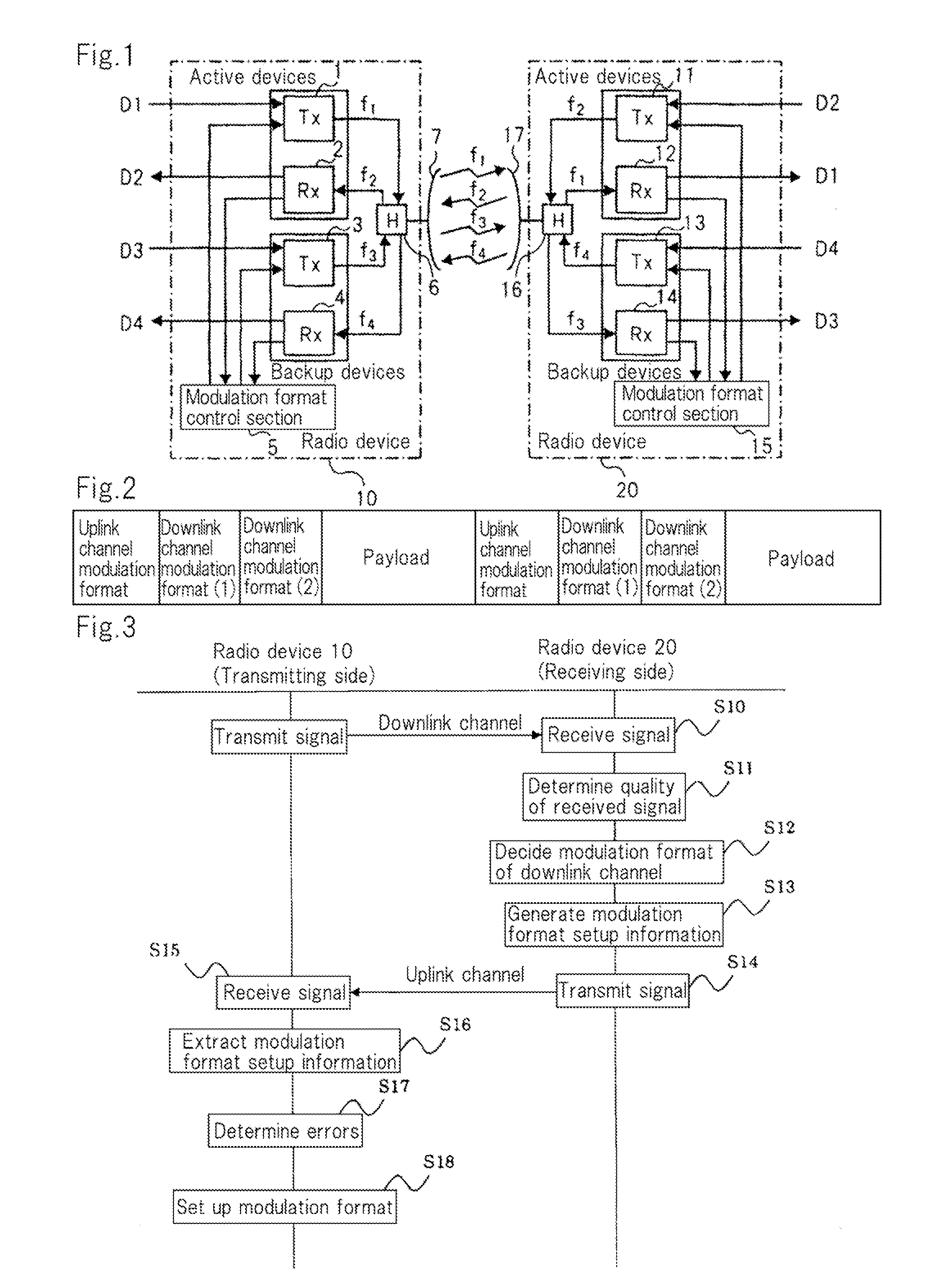
[0037]FIG. 1 is a block diagram showing a structure of a radio communication system according to a first exemplary embodiment of the present invention.

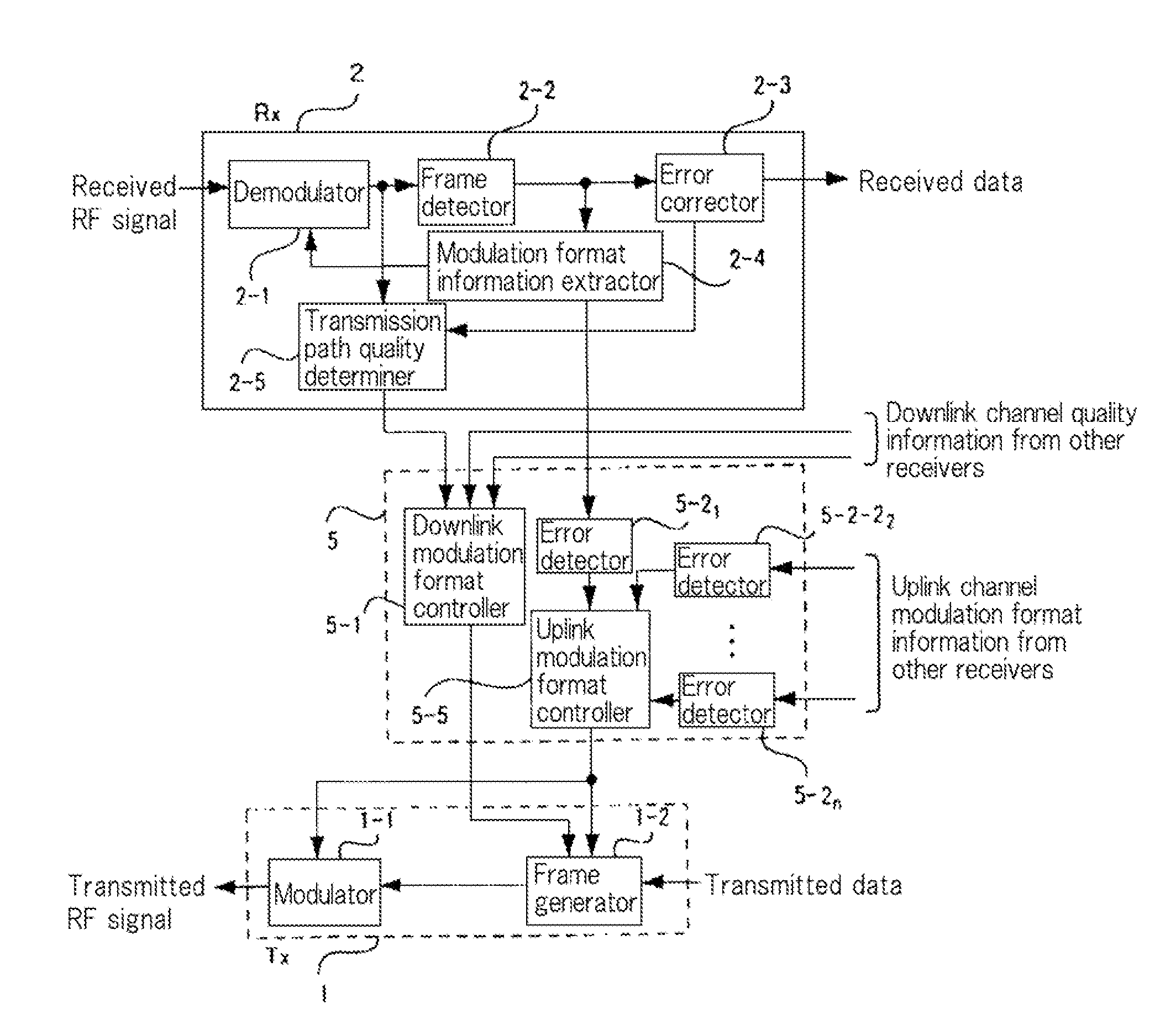
[0038]Referring to FIG. 1, the radio communication system is applicable to an FDD (Frequency Division Duplex)-based stationary microwave radio communication system and so forth, that use different frequencies for transmission and reception. The radio communication system includes radio devices 10, 20 that can mutually communicate with each other through radio channels. Radio device 10 has transmitters 1, 3, receivers 2, 4, modulation format control section 5, coupler 6, and antenna 7. Radio device 20 has transmitters 11, 13, receivers 12, 14, modulation format control section 15, coupler 16, and antenna 17.

[0039]In radio device 10, transmitter 1 and receiver 2 are active devices, whereas transmitter 3 and receiver 4 are backup devices.

[0040]Transmitter 1 outputs a transmission signal that contains data D1 and respective pieces of modu...

second exemplary embodiment

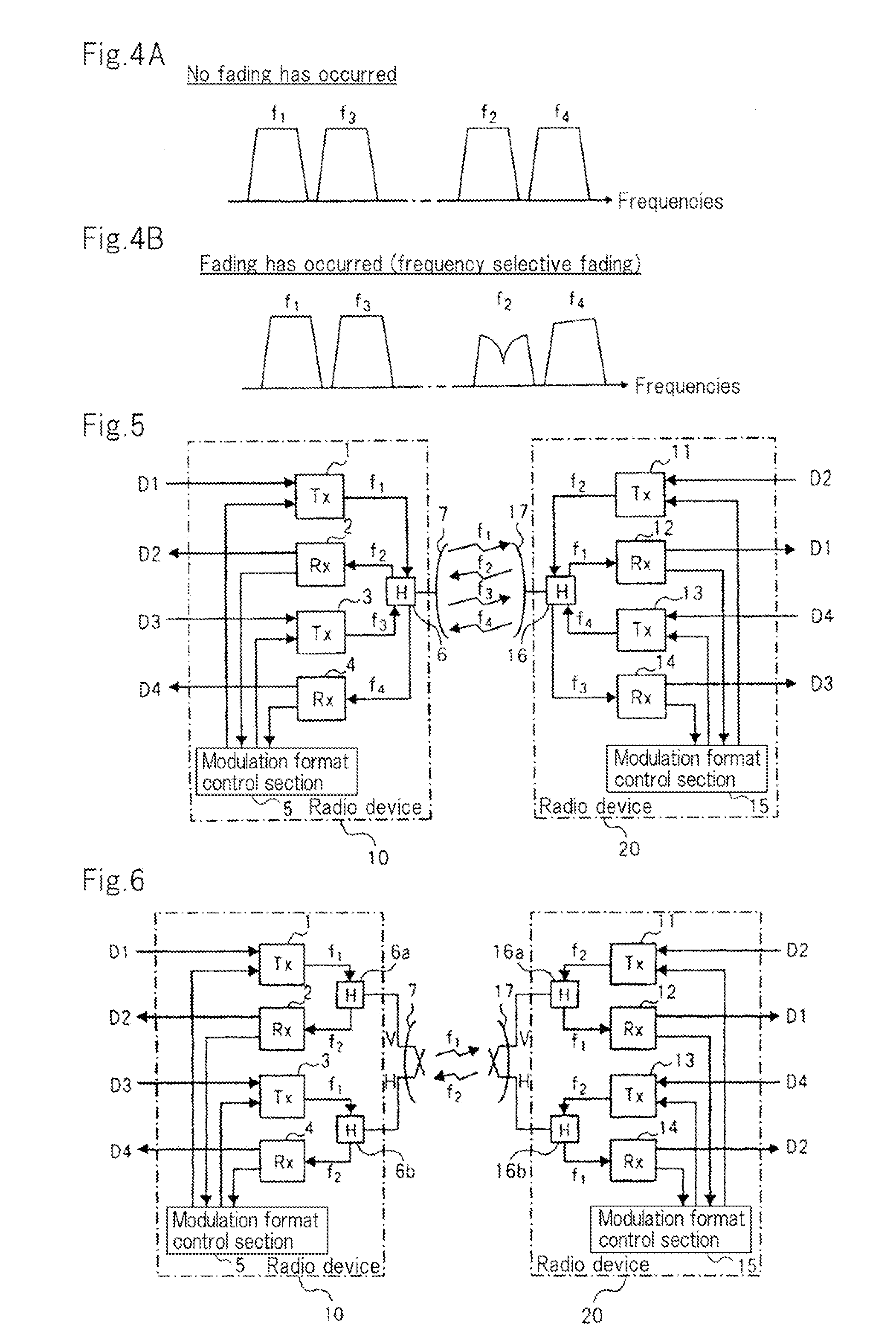
[0093]FIG. 5 is a block diagram showing a structure of a radio communication system according to a second exemplary embodiment of the present invention.

[0094]The structure of the radio communication system according to this embodiment is the same as that according to the first exemplary embodiment except that in the former, transmitters 3, 13 and receivers 4, 14 are used as active devices rather than backup devices. In other words, in the radio communication system according to the second exemplary embodiment, radio devices 10, 20 are connected through a plurality of uplink channels and a plurality of downlink channels. Since the operation of each section of radio devices 10, 20 is the same as that according to the first exemplary embodiment, their description is omitted.

third exemplary embodiment

[0095]FIG. 6 is a block diagram showing a structure of a radio communication system according to a third exemplary embodiment of the present invention.

[0096]The radio communication system according to this embodiment is different from that according to the first exemplary embodiment in that the former uses co-channel transmission. In the co-channel transmission, one channel is used, for example, as a first channel through which a vertically polarized radio signal is transmitted and a second channel through which a horizontally polarized radio signal is transmitted.

[0097]To perform the co-channel transmission, the radio communication system according to this embodiment uses couplers 6a, 6b instead of coupler 6; and couplers 16a, 16b instead of coupler 16. In this example, each of antennas 7, 17 can transmit a vertically polarized radio signal and a horizontally polarized radio signal. The other structures of the radio communication system according to this embodiment are basically th...


PUM


Abstract

A radio device (10) receives signals from a radio device (20) through a plurality of downlink channels that have different frequencies, decides modulation formats that have transmission performances based on qualities of the received signals for the individual downlink channels, and transmits modulation format setup information in which respective pieces of information that represent the decided modulation formats for the individual downlink channels are combined into one piece to the radio device (20) through a plurality of uplink channels that have different frequencies. The radio device (20) refers to modulation format setup information received through at least one of the plurality of uplink channels and sets up modulation formats for signals transmitted through the plurality of downlink channels based on the modulation format setup information.

Description

TECHNICAL FIELD[0001]The present invention relates to adaptive modulation techniques for use in radio communication systems typified by stationary microwave radio communication systems and so forth.BACKGROUND ART[0002]An adaptive modulation system is exemplified in Patent Literature 1 (JP 10-41876A, publication). This adaptive modulation system is applied to a TDMA (Time Division Multiple Access)-FDD (Frequency Division Duplex)-based radio communication system in which frequencies used for uplink and downlink channels are different.[0003]In the adaptive modulation system presented in Patent Literature 1, a receiving side station receives a signal having a frequency f1 from a transmitting side station through a downlink channel. In the receiving side station, a propagation path estimation section detects the state of a propagation path of the downlink channel based on the state of the received signal. Then, a control section decides a modulation format to be used on the downlink chan...

Claims


Application Information

Patent Timeline
IPC IPC(8): H04L27/00H04L27/04
CPCH04L1/0003H04L1/0025Y02B60/31H04L5/143H04L5/06Y02D30/50
Inventor KAWAI, MASAHIRO
Owner NEC CORP
Why Eureka
Try Eureka