Optical Adaptor

Inactive Publication Date: 2011-11-24
QIOPTIQ
View PDF1 Cites 5 Cited by
  • Summary
  • Abstract
  • Description
  • Claims
  • Application Information

AI Technical Summary

Benefits of technology

[0021]According to another aspect of the present invention, there is provided a sample viewing device comprising an optical adaptor of the type defined above, and optical imaging system, the viewing device further comprising means to support a substantially transparent sample carrier (such as a microplate) in a viewing position in which at least part of the sample carrier may be imaged by said imaging system, and wherein said optical adaptor is selectively positionable in the optical path between said sample carrier and the imaging system. The optical adaptor can thus be removed from the optical path between the sample carrier and the imaging system when the sample carrier takes the form of a microplate with flat-bottomed wells, so that the imaging system can image samples within the individual wells in a conventional manner. However, by inserting the optical adaptor of the present invention in the optical path between the sample carrier and the imaging system, the viewer can be re-configured to provide clearly focussed images of samples within the individual wells of a curved-well microplate.

Problems solved by technology

However, problems arise when microplates having wells with curved (and typically outwardly convex) bottoms are used, because the imaging system is then required to image a curved object, resulting in a curved image formation plane, thereby preventing the system from producing a well focussed image on the flat sensor.

Method used


Image

  • Optical Adaptor
  • Optical Adaptor
  • Optical Adaptor

Examples


example

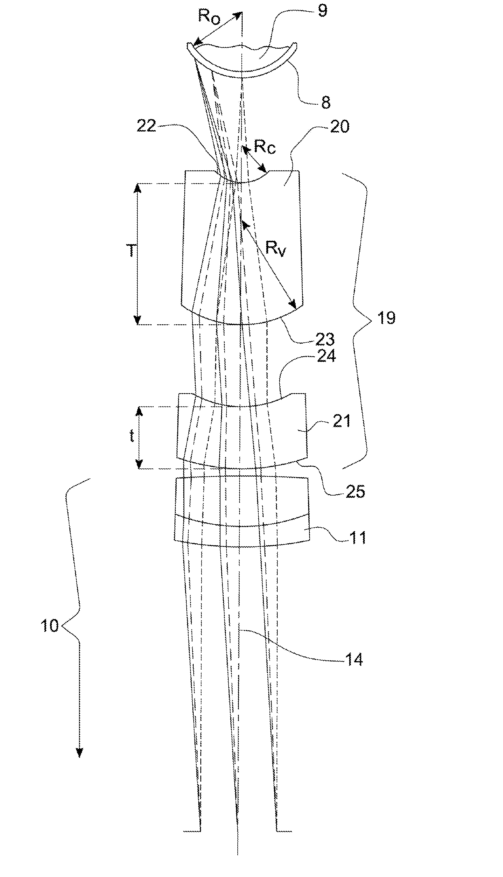
[0050]An example of a specific optical adaptor in accordance with the present invention and a base optical system is illustrated in FIG. 5 and is defined by the data set out in Table 1 below, where the optical adaptor corrects for an object having a radius of 5 mm, and where:

[0051]Surface=the lens surfaces A to N indicated in FIG. 5

[0052]R=the radii of curvature of respective lens surfaces

[0053]T=the axial thickness of the following lens material or air

[0054]Nd=the refractive index of the lens material referenced to a wavelength of 587.6 nm

[0055]Vd=the Abbe number of the lens material referenced to a wavelength of 587.6 nm

[0056]As will be appreciated, therefore, the object being viewed is located against the inside surface (i.e surface A) of a curved well of a microplate sample holder. The base optical system is a 1:1 relay and represented by surfaces G to M in Table 1 and FIG. 5, whilst the optical adaptor of the present invention is represented by surfaces C to F.

[0057]Furthermore...


PUM


Abstract

An optical adaptor is disclosed for use in combination with an optical imaging system. The adaptor is specifically configured so that when it is positioned within the optical path between an object and the imaging system, the adaptor corrects the field curvature of the imaging system so as to produce a substantially flat image of a curved object. The adaptor comprises a primary lens unit of positive power which in use is towards the object and which preferably takes the form of a thick meniscus lens having an overcorrect Petzval Sum, and a secondary lens unit of negative power which in use is towards the imaging system and which preferably takes the form of a relatively thin meniscus lens.

Description

BACKGROUND OF THE INVENTION[0001]The present invention relates to an optical adaptor, and more particularly relates to an optical adaptor suitable for use in combination with an optical imaging system so as to correct the field curvature of the imaging system when viewing a curved object so as to produce a substantially flat image of the curved object.[0002]The optical adaptor of the present invention has been developed for use with an optical viewing system of the type generally used for viewing and analysing cell cultures, and the invention is therefore described herein with specific reference to such systems. However, it should be appreciated that the invention may find use in other applications where it is desired to adjust the field curvature of a base imaging system in a manner effective to allow the imaging system to produce a focussed image of a curved object in a substantially flat image plane.DESCRIPTION OF THE PRIOR ART[0003]Sample viewing devices have been proposed previ...

Claims


Application Information

Patent Timeline
IPC IPC(8): G02B9/10
CPCG02B27/0025G02B13/24
Inventor JEFFS, MARK
Owner QIOPTIQ
Why Eureka
Try Eureka