Amazing Member and Atomizer Including the Same
a technology of atomizer and amazing member, which is applied in the field of ultrasonic atomizing member, can solve the problems of difficulty in sufficiently increasing atomization efficiency and difficulty in sufficiently reducing power consumption, and achieve the effects of reducing unnecessary vibration, reducing the angle of diffusion occurring in the vibrating membrane, and reducing the frequency of resonance near the resonant frequency of the vibrating membran
- Summary
- Abstract
- Description
- Claims
- Application Information
AI Technical Summary
Benefits of technology
Problems solved by technology
Method used
Image
Examples
first embodiment
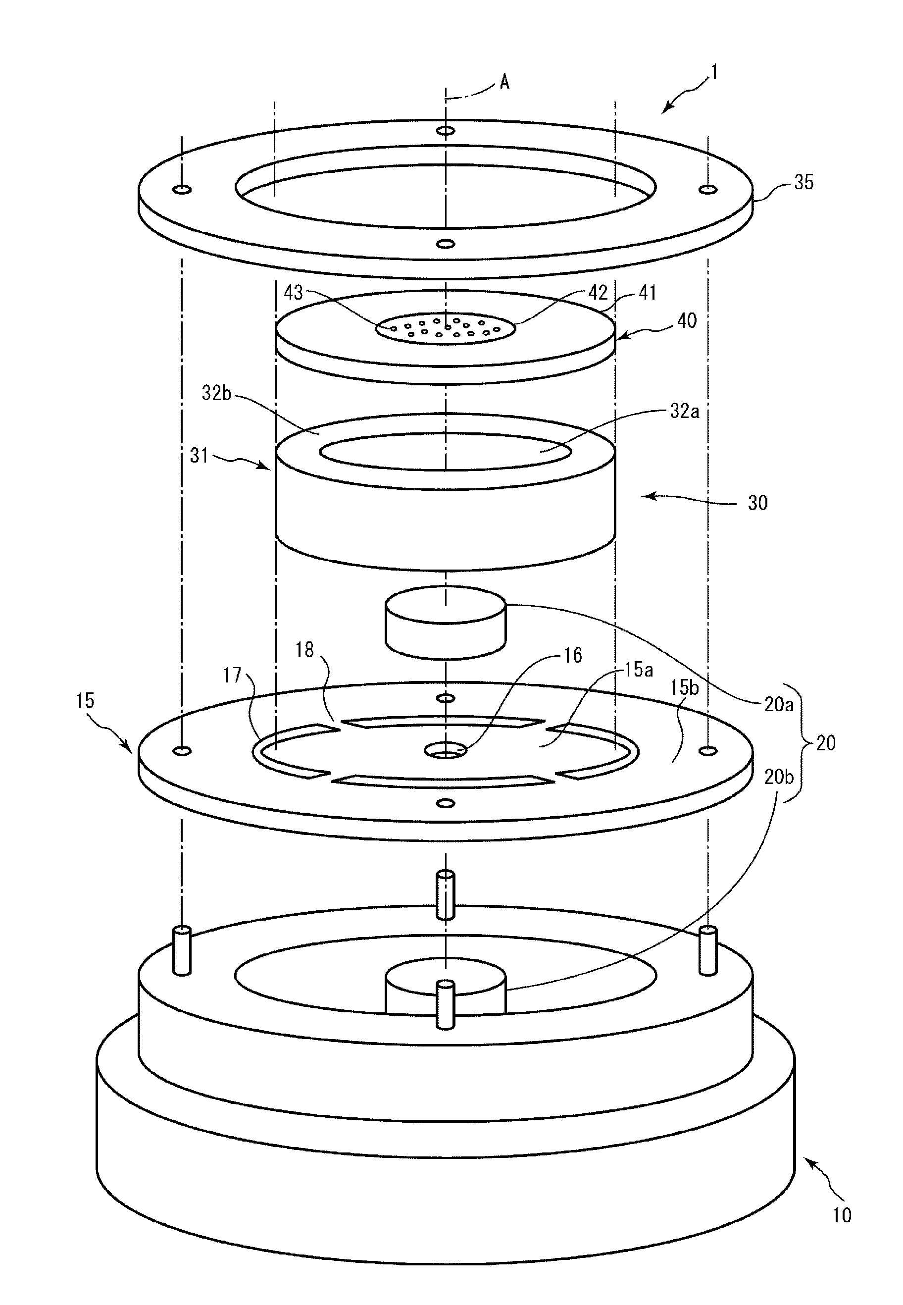
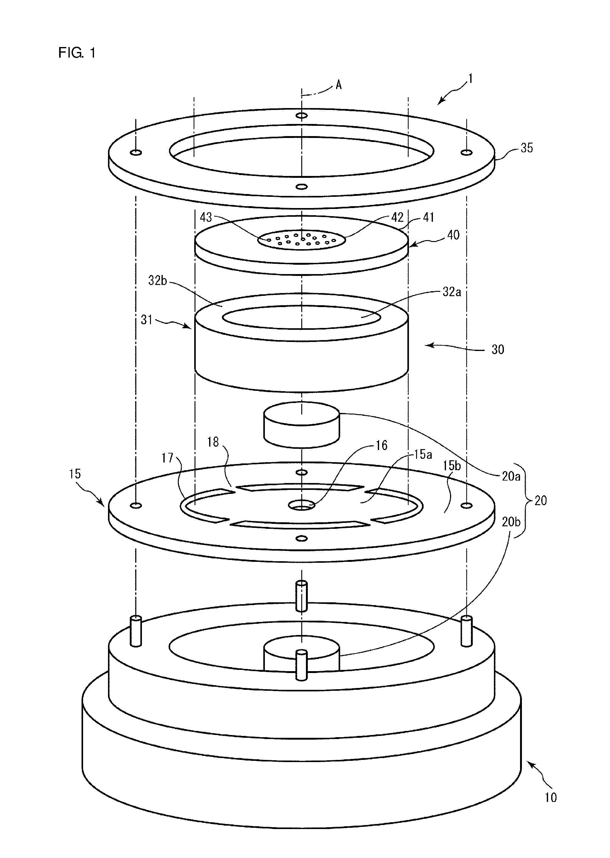
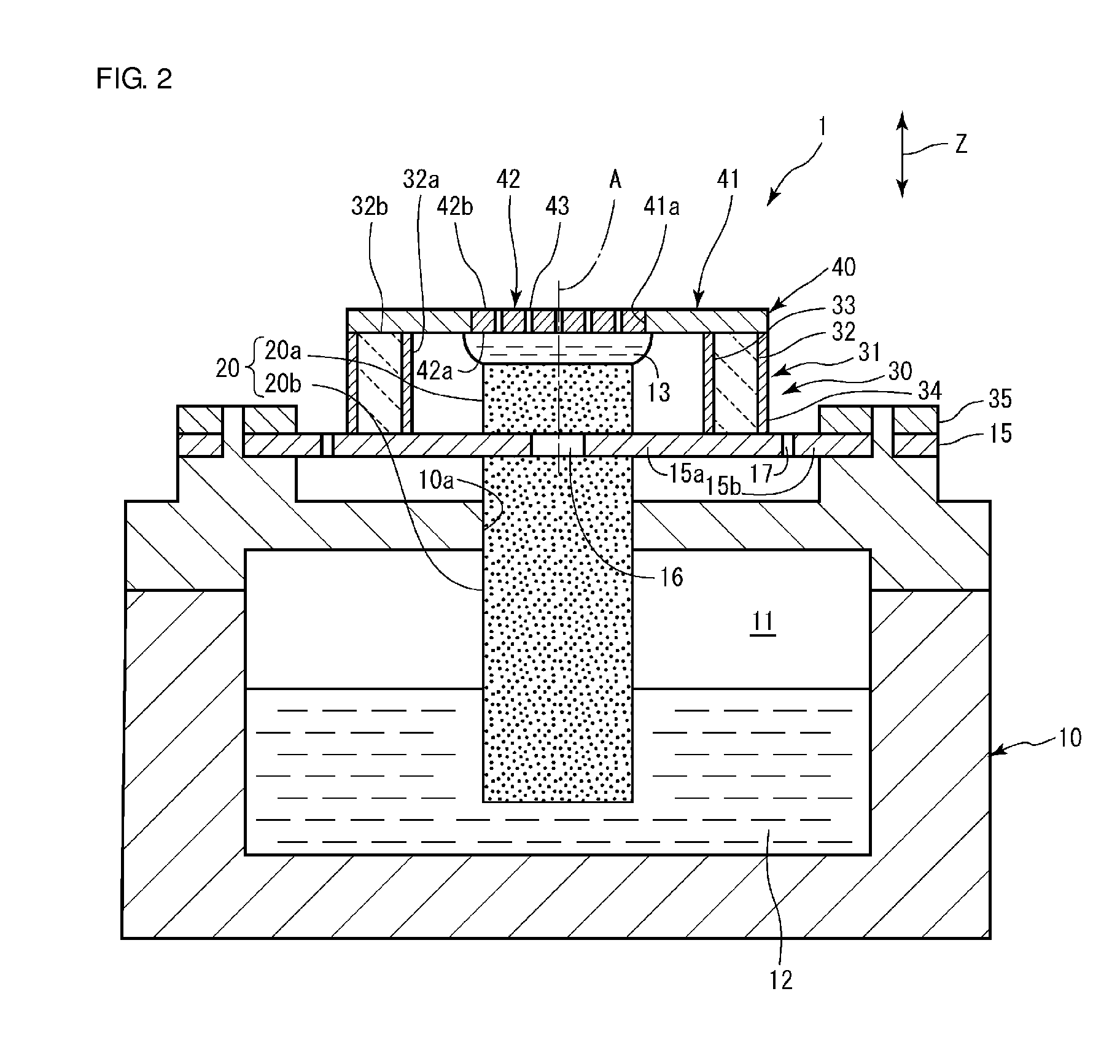
[0049]FIG. 1 is a schematic exploded perspective view of an atomizer of the first embodiment. FIG. 2 is a schematic cross-sectional view of the atomizer of the first embodiment. As illustrated in FIGS. 1 and 2, an atomizer 1 includes an atomizing member 30, an atomizer main body 10, and a liquid feeder 20. The atomizer 1 may further include a circuit for driving the atomizing member 30, for example. The circuit for driving the atomizing member 30 can have an oscillator circuit, a control circuit for the oscillator circuit, a power circuit for supplying power to each circuit, and other circuits, for example.
[0050]The atomizer main body 10 can be made of synthetic resin, metal, glass, ceramic, paper, and other materials, for example. As illustrated in FIG. 2, the atomizer main body 10 includes a storage 11 disposed therein. The storage 11 stores liquid 12 to be atomized. The liquid 12 is not particularly limited. Examples of the liquid 12 can include water, aqueous solution, and an or...
second embodiment
[0092]FIG. 6 is a schematic cross-sectional view of an atomizer of the second embodiment. FIG. 7 is a perspective view of an atomizing member of the second embodiment.
[0093]An atomizer 1a of the second embodiment has substantially the same configuration as that of the atomizer 1 of the above first embodiment, except for the form of the atomizing member 30 and the supporting manner of the atomizing member 30. In the second embodiment, sections in the atomizing member 30 other than the first and second electrodes 33 and 34 are integrally formed from ceramic. Specifically, in the second embodiment, the vibrating membrane 40, the piezoelectric body 32, and a flange 45, which is described below, are integrally formed from piezoelectric ceramic. Therefore, it is not necessary to bond the members, so the atomizing member 30 can be easily produced. The integral formation of the vibrating membrane 40, the piezoelectric body 32, and the flange 45 can improve the vibration efficiency. Accordin...
modification examples
[0103]In the above second embodiment, an example in which the flange 45 is toroidal is described. However, the shape of the flange in the present invention is not particularly limited. For example, as illustrated in FIG. 8, the flange 45 may be substantially rectangular.
[0104]In the above second embodiment, an example in which the annular groove 45a in the connection portion 45b of the flange 45 connected to the piezoelectric body 32 prevents vibration of the piezoelectric body 32 from being conveyed to the flange 45 is described. However, the method of reducing conveyance of the vibration of the piezoelectric body 32 to the flange 45 is not limited to the method using the annular groove 45a. Making vibration propagation characteristics of the connection portion 45b different from those of the sections of the flange 45 other than the connection portion 45b can reduce conveyance of the vibration of the piezoelectric body 32 to the flange 45. Examples of the method of making vibration...
PUM
 Abstract
Description
Claims
Application Information
 - R&D
- Intellectual Property
- Life Sciences
- Materials
- Tech Scout
- Unparalleled Data Quality
- Higher Quality Content
- 60% Fewer Hallucinations
Browse by: Latest US Patents, China's latest patents, Technical Efficacy Thesaurus, Application Domain, Technology Topic, Popular Technical Reports.
© 2025 PatSnap. All rights reserved.Legal|Privacy policy|Modern Slavery Act Transparency Statement|Sitemap|About US| Contact US: help@patsnap.com


