
Bone Screw Assembly and Instruments for Implantation of the Same

a technology of bone screws and screws, which is applied in the field of bone screw assemblies and instruments for implantation of the same, can solve the problems that bone screws, pins or nails can for instance become dislodged in the bon

Inactive Publication Date: 2011-11-17
DEPUY SYNTHES PROD INC
View PDF5 Cites 101 Cited by
  • Summary
  • Abstract
  • Description
  • Claims
  • Application Information

AI Technical Summary

Benefits of technology

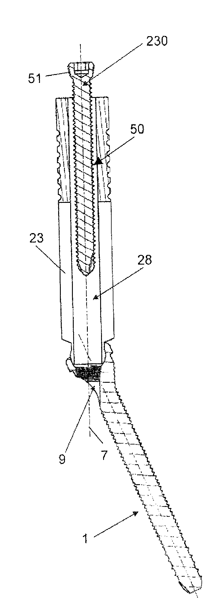
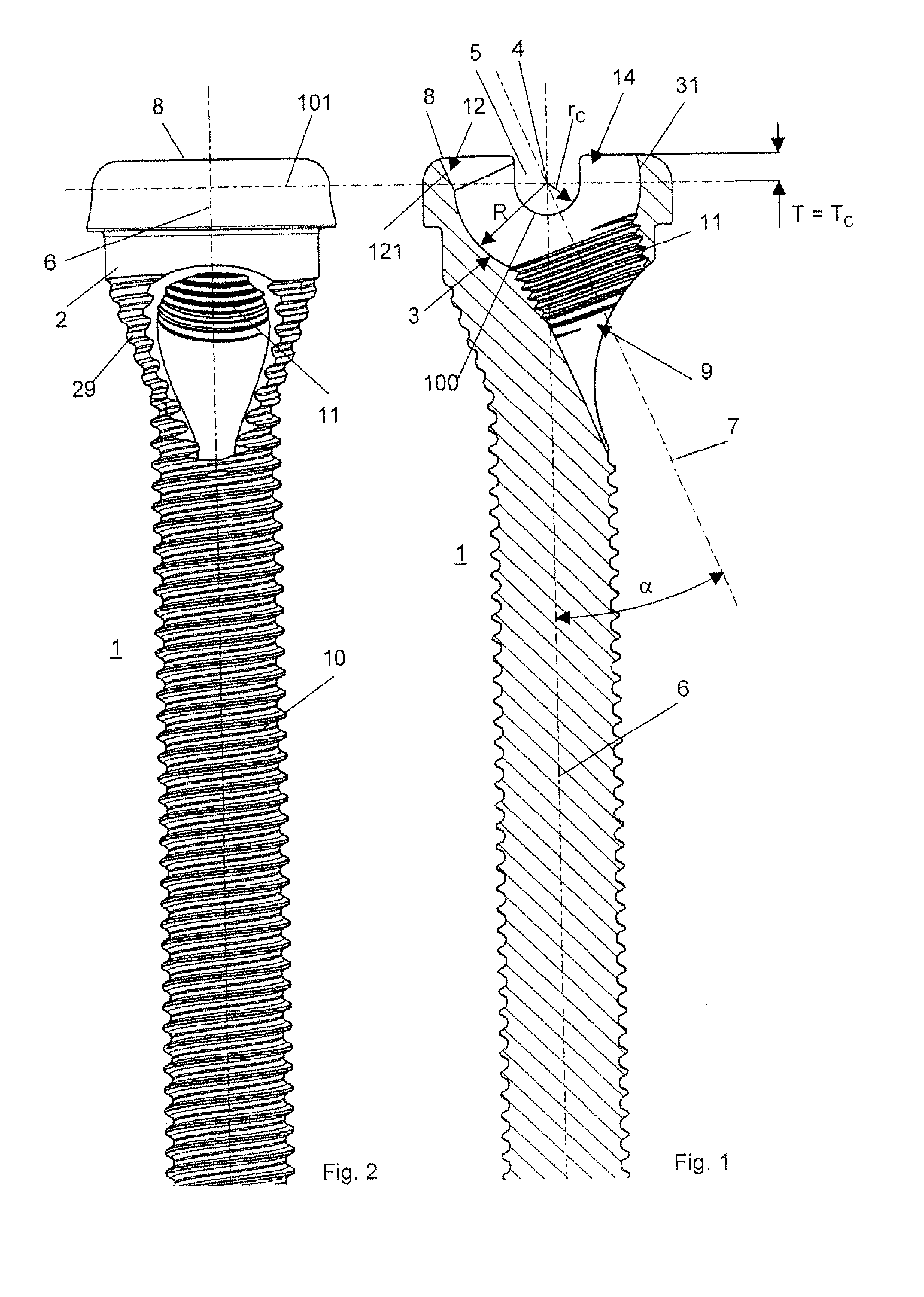
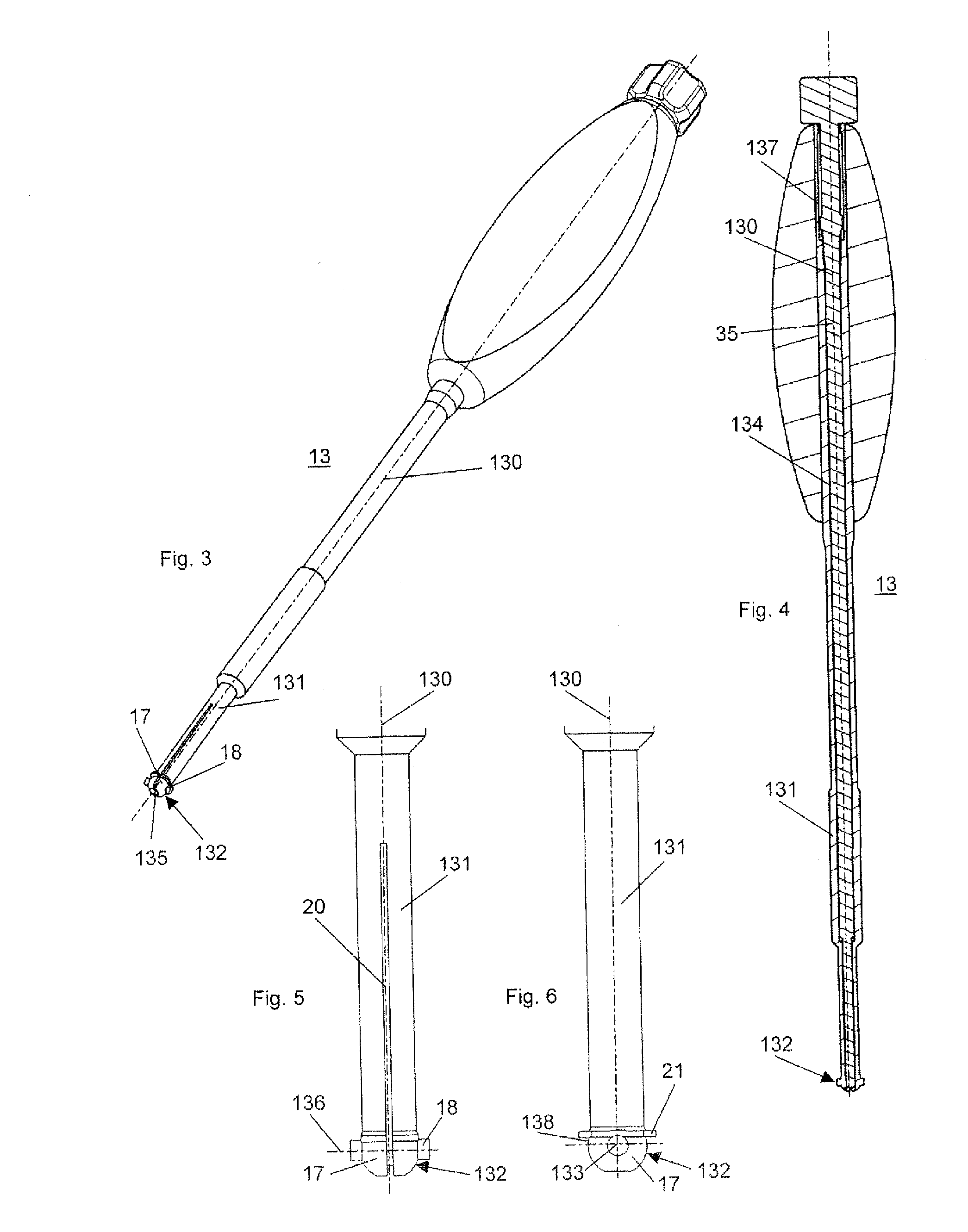
[0007]One of the advantages of the bone screw according to the invention is that the configuration of the transverse channel and the recess permits an aiming guide with a complementarily configured tip to be attached to the screw head and rotated about a rotation axis from a first position aligned with the screw axis into a second position aligned with the through hole axis. Another advantage of the bone screw is the pivotable joining of the screw head and the aiming guide. The aiming guide can be inserted into the incision coaxially to the screw axis of the bone screw by using a tissue protection tube and / or a guide wire and attached to the screw head. After removing the tissue protection tube and / or the guide wire the aiming guide can be rotated about the rotation axis. In addition, the aiming guide can then be rotated into a second position in which the longitudinal axis of the aiming guide is aligned with the through hole axis of the through hole in the screw head so that a bore hole for the second screw can be drilled into the bone which is exactly aligned with the through hole in the screw head; the bore hole for the second screw can be drilled in a completely guided manner and the second screw can be positioned in a guided manner by means of the aiming guide. Another advantage is that the transverse channel and the recess allow to attach a complementarily formed tip of a screwdriver to the bone screw in such a manner that the screwdriver is positioned coaxially to the screw axis of the bone screw.
[0030]In an exemplary embodiment, the aiming guide further comprises a longitudinal slot extending parallel to the longitudinal axis and which is open at the front end so that the connector is radially elastically compressible. Additionally, a curved contact shoulder is formed at the proximal end of the tip. Specifically, the curved contact shoulder is formed by a constriction at the proximal end of the tip (adjacent the guide sleeve) where a cross-sectional area of the tip in a plane orthogonal to the central axis of the tip is reduced relative to a maximum diameter portion of the tip distal thereto. This configuration allows the connector to operate as a male connector for a snap-lock connection with a respective female connector arranged in the bone screw.

Problems solved by technology

One problem that can arise in case of the above mentioned bone fixation devices is that the bone screws, pins or nails can for instance become dislodged in the bone or in the bone plate, intervertebral implant or intramedullary nail during normal movements of the patient.

Method used


Image

  • Bone Screw Assembly and Instruments for Implantation of the Same
  • Bone Screw Assembly and Instruments for Implantation of the Same
  • Bone Screw Assembly and Instruments for Implantation of the Same

Examples


Embodiment Construction

[0087]The present invention may be further understood with reference to the following description and the appended drawings, wherein like elements are referred to with the same reference numerals. The present invention relates to bone screw assemblies and instruments for implantation of the same as well as to an associated method for implantation of the bone screw assembly using the instruments. In particular, the invention relates to a system and method facilitating implantation of a first bone screw, including a through hole extending through a head portion thereof along a through hole axis, and a second screw inserted into the through hole along the through hole axis such that the first and second bone screws are implanted into a bone in a stable configuration.

[0088]FIGS. 1 and 2 illustrate an embodiment of the bone screw 1 with a screw head 2 comprising a conical external thread 29. The bone screw 1 includes a screw axis 6, a threaded shaft 10, a screw head 2 and a rear end 8 at...


PUM


Abstract

A bone screw includes a screw shaft extending longitudinally along a screw axis and a screw head extending from a proximal end of the screw shaft and configured to be releasably coupled to a surgical tool. The bone screw also includes a through hole defining a through hole axis and extending through the screw head, the through hole axis intersecting the screw axis at an acute angle α, the through hole being adapted to receive therein a second screw and tapering from a first end at a proximal end of the screw head to a second end opening to an outer surface of the screw head.

Description

PRIORITY CLAIM[0001]The present invention claims priority to U.S. Provisional Application Ser. No. 61 / 334,234 filed on May 13, 2010 and entitled, “Bone Screw Assembly and Implantation of the Same,” the entire disclosure of which is incorporated herein by reference.FIELD OF THE INVENTION[0002]The present invention generally relates to bone screw assemblies and instruments for implantation of the same as well as to an associated method for implantation of the bone screw assembly using the instruments. More particularly, the invention relates to a bone screw including a second screw and insertion instruments for implantation of the same as well as to a method for implantation of the bone screw and the second screw by using the insertion instruments.BACKGROUND[0003]In the field of orthopedic surgery bone fixation devices using bone screws are commonly used. These bone fixation devices include bone plates, intervertebral implants or intramedullary nails by means of which two or more bone...

Claims


Application Information

Patent Timeline
IPC IPC(8): A61B17/86
CPCA61B17/725A61B17/7258A61B17/861A61B2017/90A61B17/8877A61B17/8888A61B17/8685A61B17/90A61B17/17A61B17/86A61B17/88
Inventor OVERES, TOMZURSCHMIEDE, SILASFLURI, DANIEL
Owner DEPUY SYNTHES PROD INC
Learn More