
Detection of gaze point assisted by optical reference signal

a technology of optical reference signal and detection system, which is applied in the field of human eyetracking devices, can solve the problems of new technological challenges, complicated and fragile devices of available eye trackers, and their operation, and achieve the effects of reducing energy consumption, facilitating deployment, and increasing tim

Active Publication Date: 2011-11-17
TOBII TECH AB
View PDF43 Cites 112 Cited by
  • Summary
  • Abstract
  • Description
  • Claims
  • Application Information

AI Technical Summary

Benefits of technology

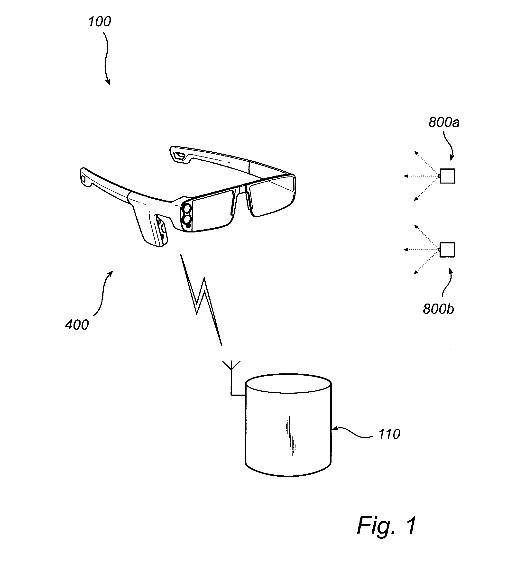
[0014]A system according to the invention is easy to set up, is failsafe and provides accurate gaze-point data. Part of the robustness of the measurements is owed to the eye glasses' capability of jointly determining the locations of the IR signal sources and the gaze direction of a person wearing the glasses. The camera unit of the eye glasses (or, respectively, the external scene camera) is adapted to provide a picture of the test scene, relative to which a gaze point can be calculated. Preferably, the eye-tracking unit and the image sensor are rigidly connected to the eye glasses or to one another. This is because their measurements are performed in separate reference frames, which would lack a stable interrelation if their relative orientations and positions were allowed to change between or during measurements. In alternative embodiments, wherein the eye-tracking unit and the image sensor are mobile with respect to one another, there are provided position and orientation indicators or functionally equivalent devices to furnish the information needed for interrelating the reference frames.
[0027]In situations where a large number of test subjects participate in an eye-tracking-assisted study, efficient collection and presentation of the data are essential. Hence, a system according to the invention—and adapted with special regard to such studies—may comprise a plurality of individual user equipments (several pairs of eye glasses), so that more than one user at a time can look at the test scene while being monitored with respect to gaze point. Most expediently, however, such a multi-subject system comprises one single data processing and storage unit, so that gaze-point information for all users is gathered in one location. This facilitates statistical analysis of the entire amount of gaze-point information. Additionally, gaze-point data for all test subjects can be conveniently presented with respect to a single picture of the test scene, the picture being acquired by any one of the eye glasses of the system or by an external imaging device, as appropriate.

Problems solved by technology

This emerging use of eye trackers leads to new challenges on the technological level.
For instance, available eye trackers are usually complex and fragile devices, and their operation may be demanding—at least to a user having a background in areas such as marketing studies or behavioural sciences rather than a relevant technological field.
The applicability of eye-tracking technology to high-volume studies is limited by two facts in particular.
Firstly, adapting an eye tracker to a new person may be a time-consuming and technologically demanding exercise, and secondly, many potential test subjects may feel hesitant or reluctant to using such a device if its interface is complicated or physically intrusive.
Indeed, from the point of view of marketing research, eye-tracking-based studies may be of interest in any environment where consumers receive visual information on which to base their buying decisions, and the range of possible psychological experiments to which eye-tracking technology is applicable seems unlimited.

Method used


Image

  • Detection of gaze point assisted by optical reference signal
  • Detection of gaze point assisted by optical reference signal
  • Detection of gaze point assisted by optical reference signal

Examples


Embodiment Construction

[0047]With reference generally to FIGS. 1-8, the constituent parts of a gaze-point detection system 100 according to the invention will now be described. As shown in FIG. 1, the system 100 includes a pair of eye glasses 400, two IR signal sources 800 (although the system could have included any number of IR signal sources) and a data processing and storage unit 110. The IR signal sources 800 are adapted to emit IR light which can be received by the eye glasses 400. The eye glasses 400 on their part are operable to communicate (uni- or bidirectionally) with the data processing and storage unit 110.

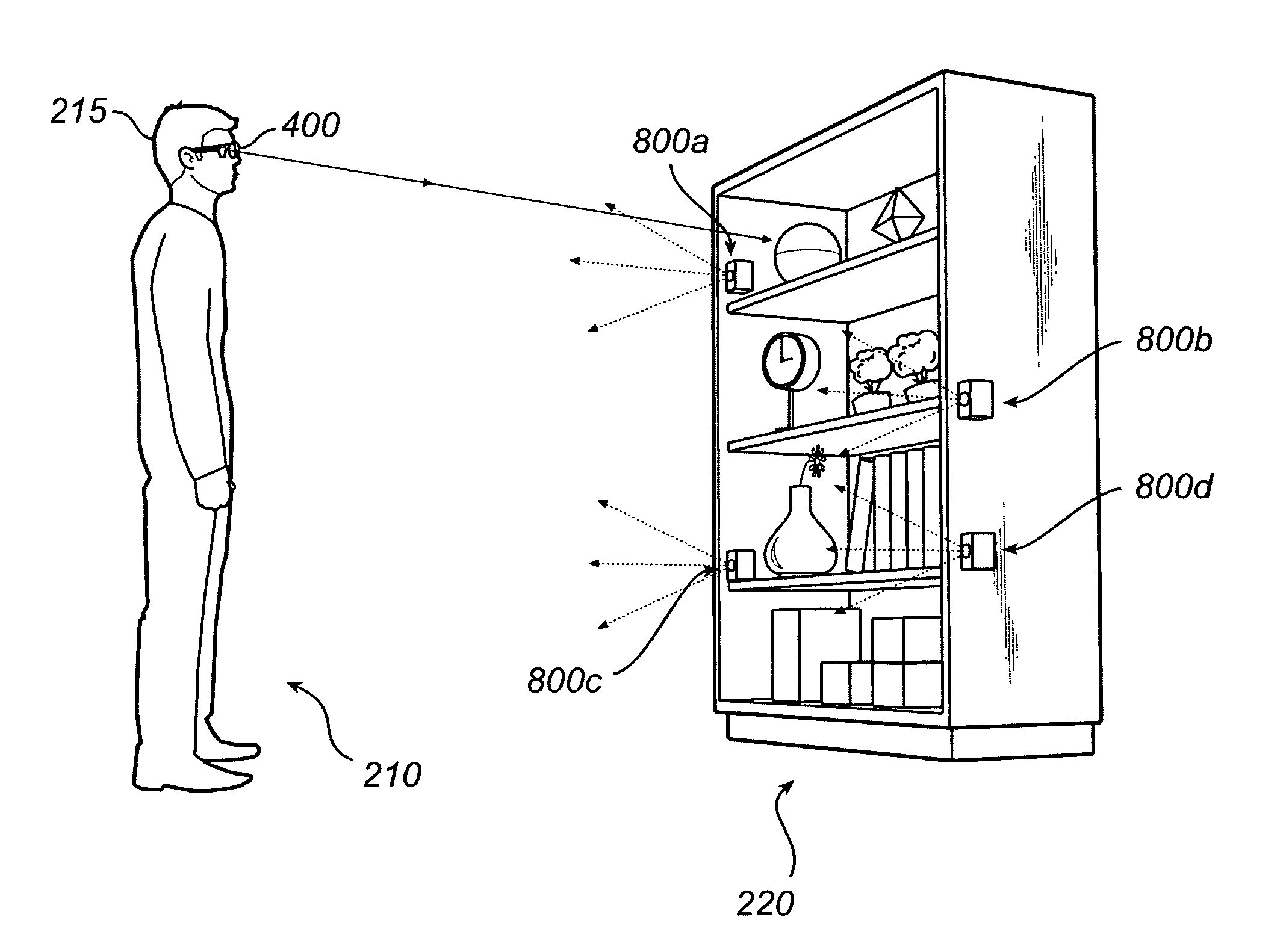
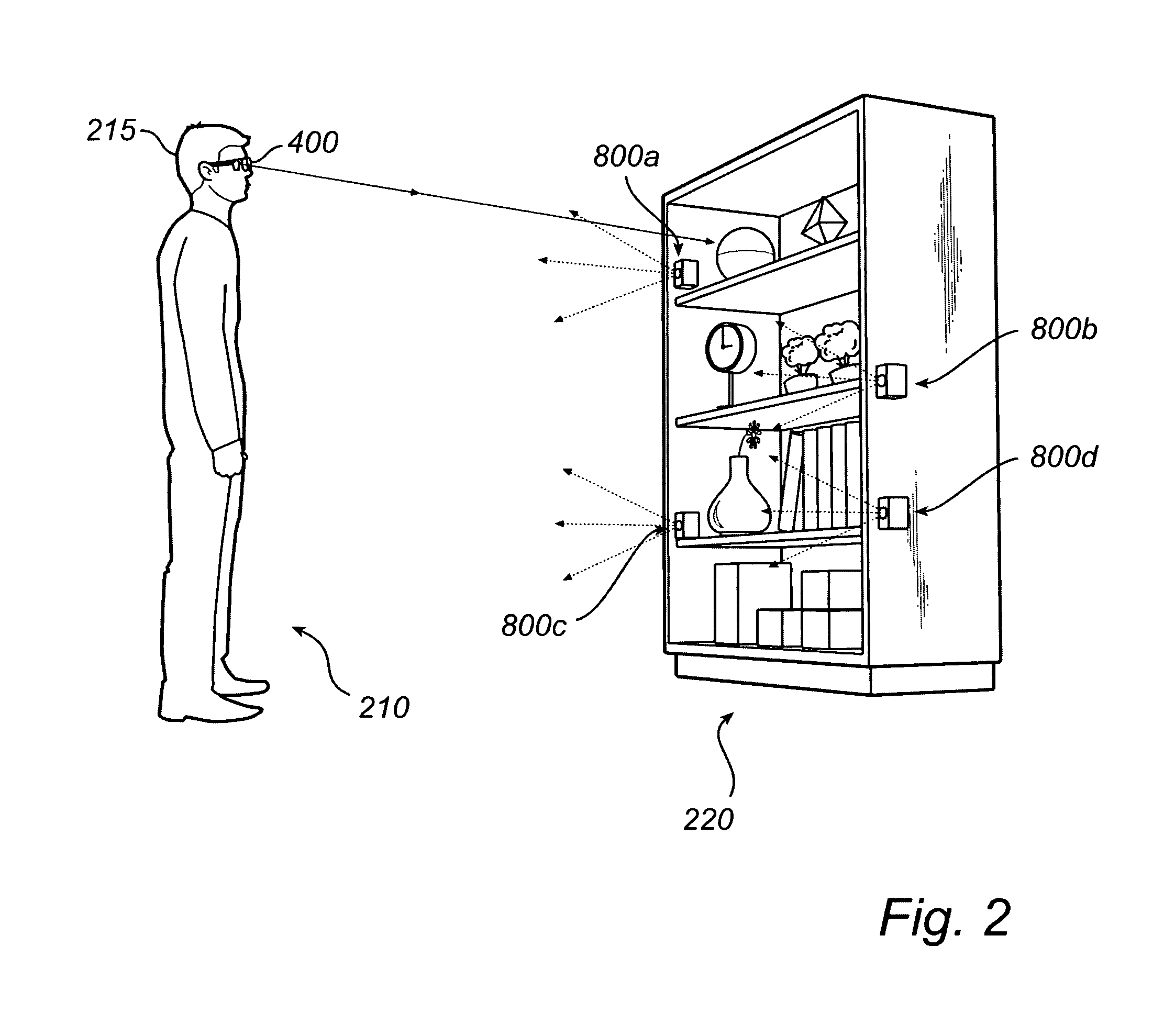
[0048]FIG. 2 shows the same system 100 applied to an exemplary measurement situation. The eye glasses 400 of FIG. 1 are worn by a person (test subject) 210. The eye glasses 400 are adapted to fit snugly onto the person's 210 head 215, so that little relative movement is possible. If the eye glasses are overly mobile with respect to the head 215 of the person 210, then the accuracy of the ga...


PUM


Abstract

A gaze-point detection system includes at least one infrared (IR) signal source to be placed in a test scene as a reference point, a pair of eye glasses to be worn by a person, and a data processing and storage unit for calculating a gaze point of the person wearing the pair of eye glasses. The pair of eye glasses includes an image sensor, an eye-tracking unit and a camera. The image sensor detects IR signals from the at least one IR signal source and generates an IR signal source tracking signal. The eye-tracking unit determines adapted to determine the gaze direction of the person and generates an eye-tracking signal, and the camera acquires a test scene picture. The data processing and storage unit communicates with the pair of eye glasses and calculates the gaze point relative to the test scene picture.

Description

FIELD OF THE INVENTION[0001]The invention generally relates to human eye-tracking devices and more particularly relates to a gaze-point detection system which is assisted by reference signals emitted by optical sources provided in the scene under viewing.BACKGROUND[0002]Monitoring or tracking eye movements and detecting a person's gaze point (as used herein, the point in space at which the person is looking) can be used in many different contexts. Such measurements can be an important information source in analysing the behaviour and consciousness of the person. The information can be used both for evaluating a test scene (as used herein, the visual percept of a region of space in which visible objects or surfaces may be present and inside which a gaze point can be detected) observed by a person, and for evaluating characteristics of the respective person. The diverse uses of gaze point detection include studies on the usability of software and different types of interfaces; evaluat...

Claims


Application Information

Patent Timeline
IPC IPC(8): H04N7/18
CPCG06K9/00604A61B3/113G06V40/19A61B3/00A61B3/12H04N7/18
Inventor STROMBOM, JOHANGUSTAFSSON, SIMONSKOGO, MARTENHOLTZ ELVESJO, JOHN MIKAELNYSTEDT, PERBLIXT, PETER
Owner TOBII TECH AB
Learn More