
Electrostatic Aerosol Concentrator

Active Publication Date: 2011-11-17
CFD RES COPORATION
View PDF11 Cites 11 Cited by
  • Summary
  • Abstract
  • Description
  • Claims
  • Application Information

AI Technical Summary

Benefits of technology

[0018]FIG. 8 is a graph showing the calculated relationships between four concentrator performance measures with increasing electrode potent

Problems solved by technology

Requirements for these two separate steps, however, are divergent and often conflicting.
This difference between the sampling and sensing volumes can lead to false alarms, reduced sensitivity and increased logistical burden.
While sample volumes may be reduced after bioaerosol collection, this adds significantly to the cost and complexity of the detection system.
Use of these mechanisms, however, often includes high impaction losses in the flow modification region, low enrichment of particles, especially for particles <2 μm in diameter, low viability of microorganisms, and high cost of operation and manufacturing.
Sample loss due to impingement in impactors can lead to poor detection sensitivity and high signal-to-noise ratios leading to false alarms.
In addition, inertial systems lack flexibility and require significant redesign if specifications such as sampling to parameters are altered.
No existing devices use electrostatics to focus aerosol particles from an air stream into a smaller volume or to concentrate aerosol particles to form a high concentration aerosol.

Method used


Image

  • Electrostatic Aerosol Concentrator
  • Electrostatic Aerosol Concentrator
  • Electrostatic Aerosol Concentrator

Examples


Embodiment Construction

[0020]The term “aerosol” as used herein is an airborne liquid, solid, or suspension and includes bacteria, molds, viruses, and spores. The term “aerosol particle” is used to describe a single solid particle, a liquid droplet, or a droplet of suspension. “Viability” of biological sample is used herein to describe the ability of a living organism or a virus to reproduce when placed in appropriate culture media.

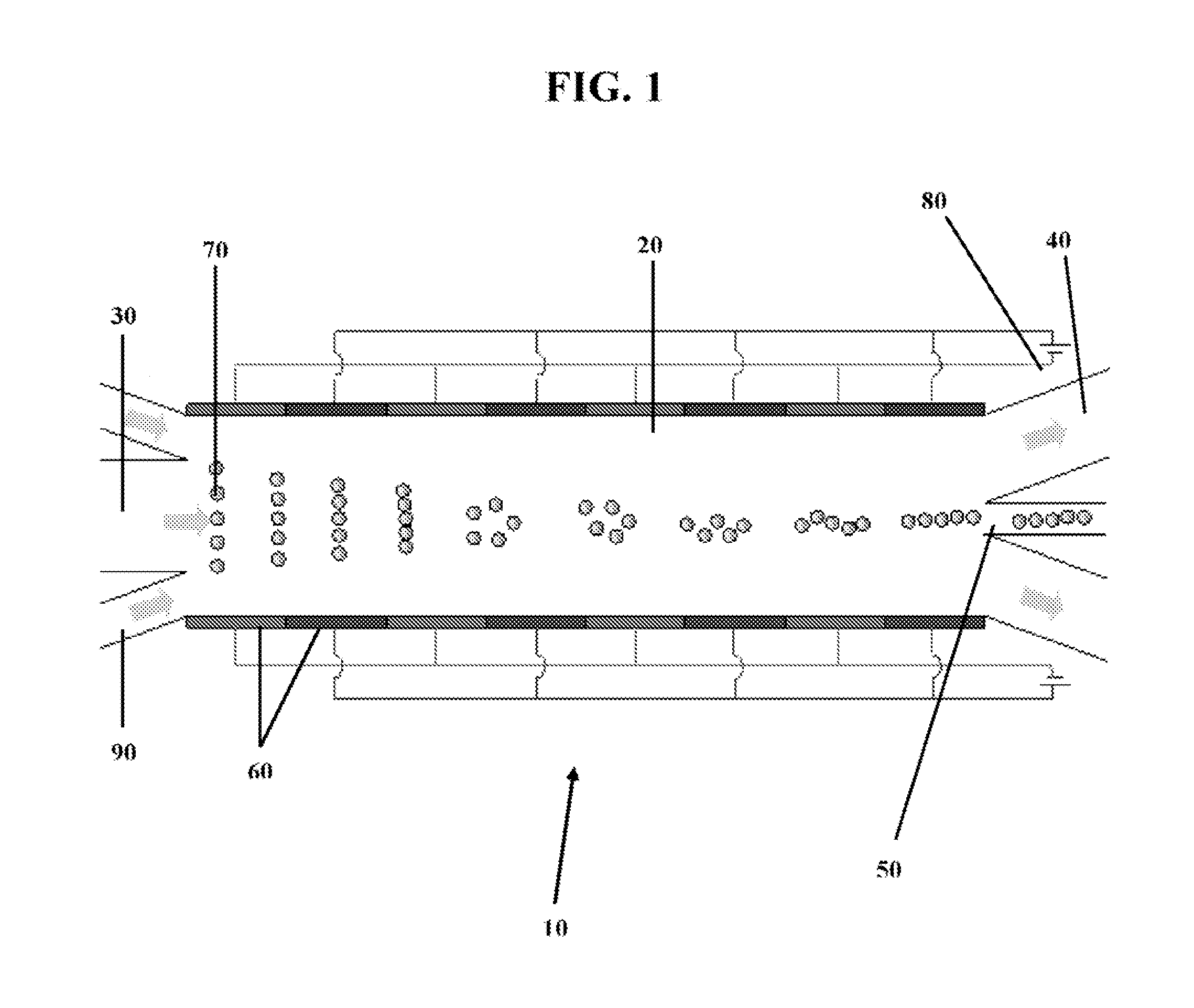
[0021]A transverse cross-section of a basic design for an apparatus for electrostatically enhanced air-to-air concentration is shown in FIG. 1. The concentrator 10 comprises an airflow chamber 20 comprising an aerosol inlet 30, an aerosol lean outlet 40, and an aerosol rich outlet 50. The wall of airflow chamber 20 comprises alternately energized and grounded electrode elements 60 that are arranged to work in concert to impart radial inward motion to charged particles 70, thereby focusing the particles toward aerosol rich outlet 50. The embodiment in FIG. 1 comprises rings of el...


PUM


Abstract

Disclosed is an electrostatic aerosol concentrator for the concentration of aerosol particles and their collection for subsequent analysis. The concentrator comprises an airflow chamber that includes alternately energized and grounded electrode elements that work in concert to impart radial inward motion to charged aerosol particles and focusing them toward an enriched aerosol outlet. If desired, filtered air inlets may be used to provide a sheath of aerosol-free air along the chamber periphery and prevent deposition of particles onto electrode surfaces. Aerosol particles entering the airflow chamber may carry a positive or negative charge naturally, or a charge may be induced on the particles using a charging section located upstream of the aerosol inlet. Natural or induced charges on the aerosol particles may be used to selectively concentrate subpopulations of aerosol particles from a mixture of particles. For example, bacterial spores or aerosolized viruses may be selectively enriched without concentrating other aerosol particles. The particles of interest are focused and collected at an aerosol rich outlet in a small air volume, while the majority of the airflow, stripped of particles of interest, is purged to the atmosphere through an aerosol lean outlet.

Description

STATEMENT REGARDING FEDERALLY SPONSORED RESEARCH OR DEVELOPMENT[0001]The U.S. Government has rights in this invention pursuant to Contract Number NBCHC060091.CROSS-REFERENCE TO RELATED APPLICATIONS[0002]Not ApplicableINCORPORATED-BY-REFERENCE OF METARIAL SUBMITTED ON A COMPACT DISC[0003]Not ApplicableBACKGROUND OF THE INVENTION[0004]1. Field of the Invention[0005]The present invention related to the concentration of aerosol particles and their collection for analysis. In particular, the invention is an air-to-air electrostatic aerosol concentrator that facilitates the collection of aerosol particles for analysis[0006]2. Description of Related Art[0007]Existing integrated bioaerosol detection systems employ a two-step process in which microorganism-containing aerosol particles are collected and targets of interest are detected. Requirements for these two separate steps, however, are divergent and often conflicting. Most bio-analytical systems used for detection are based on liquid sa...

Claims


Application Information

Patent Timeline
IPC IPC(8): B03C3/45B03C3/00
CPCB03C3/025B03C3/06B03C3/68B03C3/49B03C3/41
Inventor PANT, KAPILSUNDARAM, SHIVSHAKARWANG, YI
Owner CFD RES COPORATION
Learn More