
Steam generator

a steam generator and flow passage technology, applied in lighting and heating equipment, applications, lighting and heating arrangements, etc., can solve the problems of increasing the amount of water scale accumulated in the flow passage, lowering the flow rate of the flow passage, and affecting the heating efficiency of the steam generator. , to achieve the effect of prolonging the lifespan of the steam generator

Inactive Publication Date: 2011-11-10
CHEN HSI FU
View PDF6 Cites 24 Cited by
  • Summary
  • Abstract
  • Description
  • Claims
  • Application Information

AI Technical Summary

Benefits of technology

[0007]The present invention has been accomplished under the circumstances in view. It is the main object of the present invention to provide a steam generator, which removes water scale automatically, avoiding water scale accumulation in the flow passage to affect steam generating performance, and prolonging steam generator lifespan.
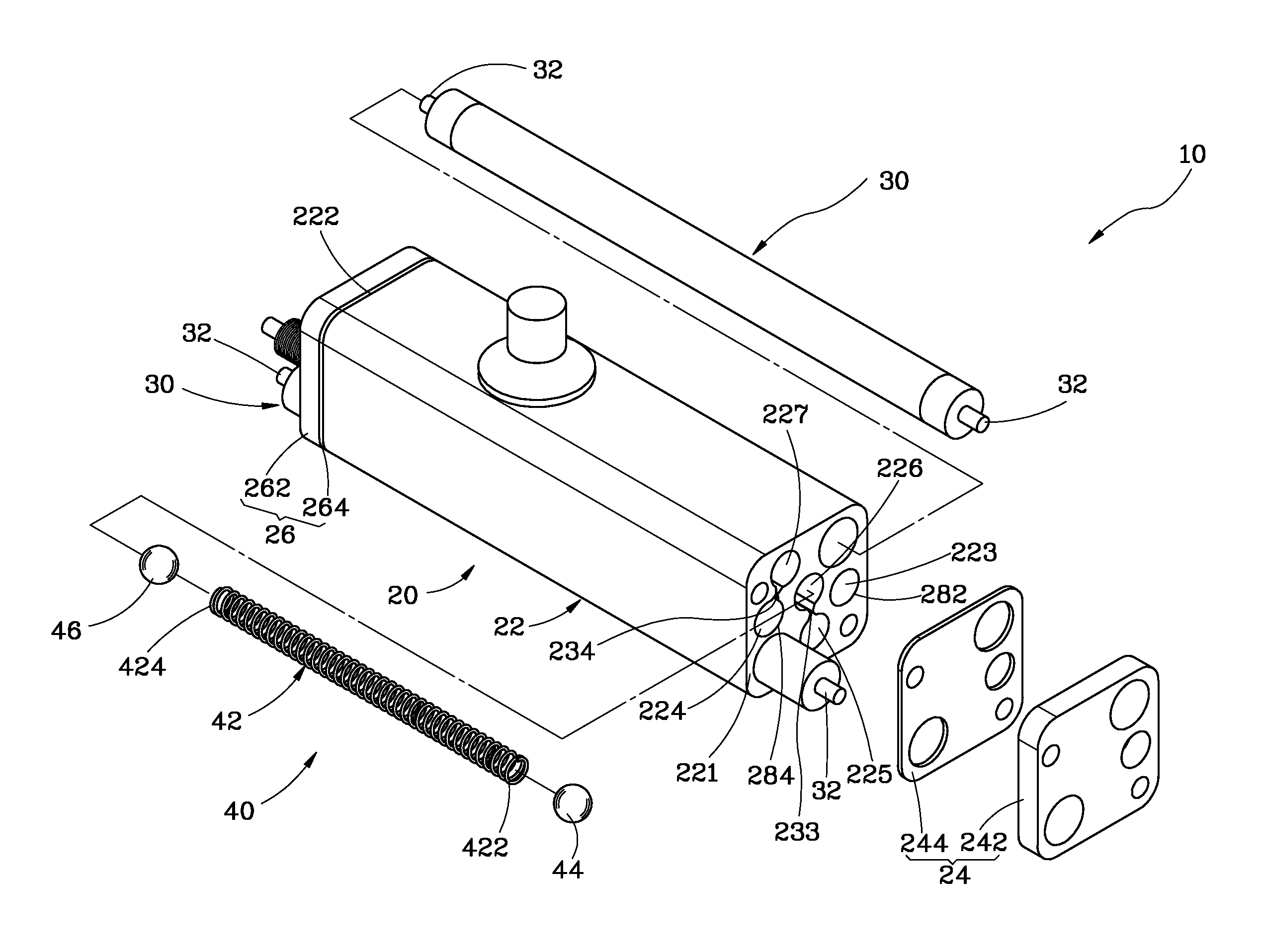
[0008]To achieve this and other objects of the present invention, a steam generator comprises a body defining therein a flow passage having an inlet and an outlet, a heater installed in the body and adapted for heating water being guided through the inlet of the flow passage into the inside of the flow passage into steam for enabling generated steam to flow out of the outlet of the flow passage, and at least one friction unit mounted in the flow passage and movable by generated steam to rub against the inside wall of the flow passage and to remove water scale from the inside wall. Thus, the steam generator uses the friction unit to remove water scale from the inside wall of the flow passage during operation, avoiding water scale accumulation and prolonging the lifespan.

Problems solved by technology

However, the inside wall of the flow passage tends to be covered with water scale.
The amount of water scale accumulated in the flow passage will increase with time, lowering the flow rate of the flow passage and affecting the heating efficiency of the steam generator.
Further, cleaning of the flow passage is not easy.
When the steam generating efficiency of the steam generator becomes low due to water scale accumulation, the steam generator must be replaced.
Replacing the steam generator increases the user's expenditure and causes inconvenience to the user.

Method used


Image

  • Steam generator
  • Steam generator
  • Steam generator

Examples


Embodiment Construction

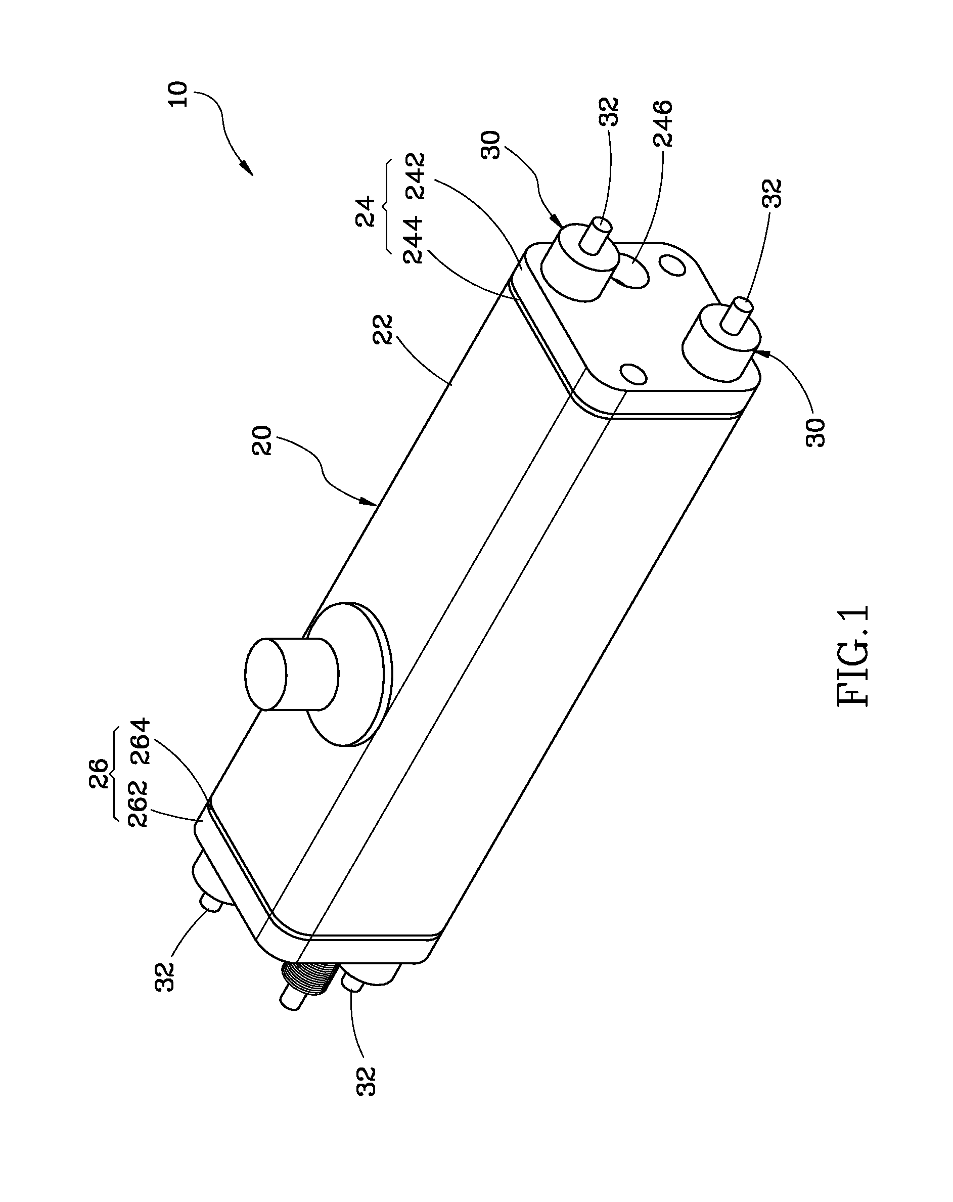
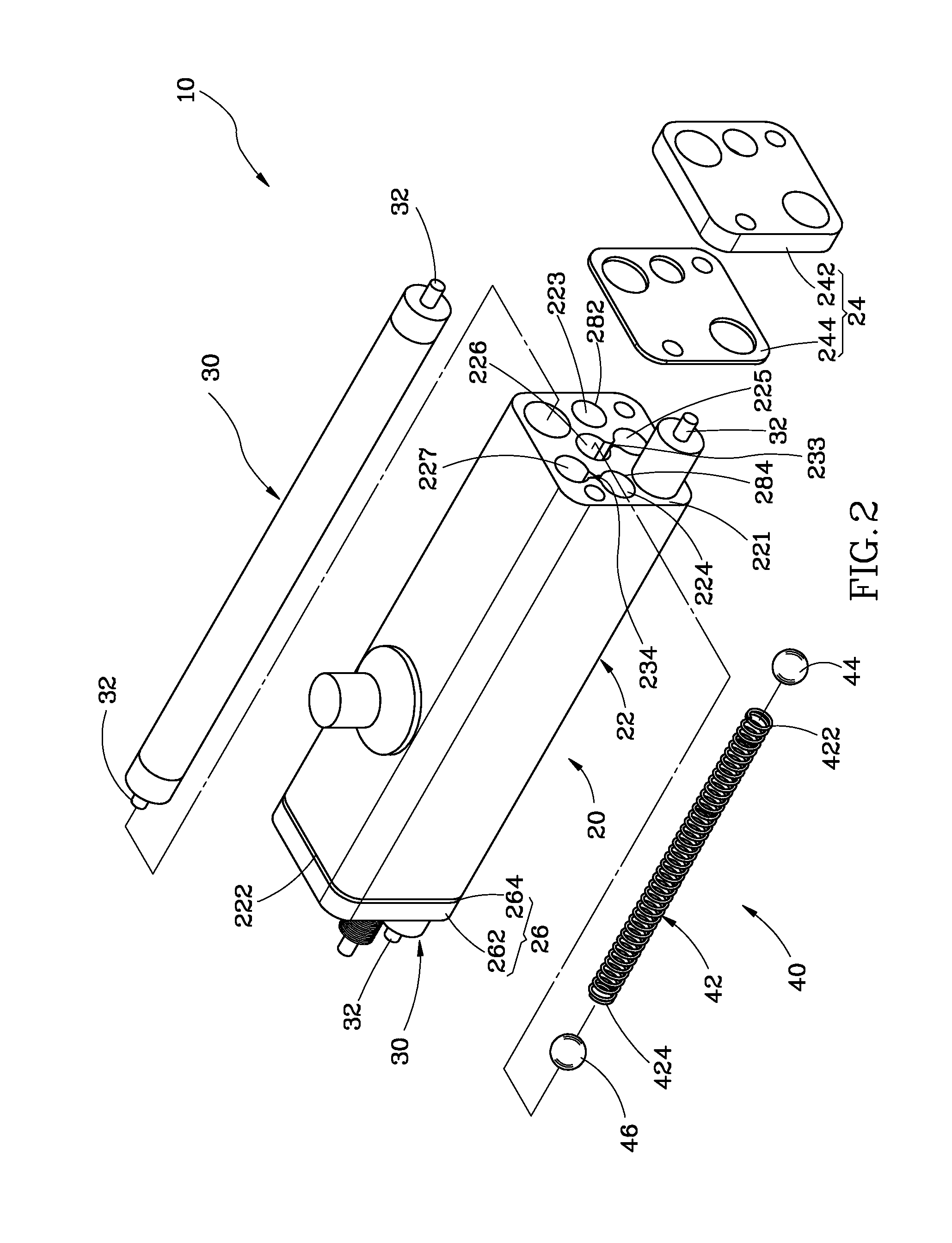
[0014]Referring to FIGS. 1-3, a steam generator 10 in accordance with the present invention is shown comprising a body 20, two heaters 30 and five friction units 40.

[0015]The body 20 comprises a base member 22, a first cover 24 and a second cover 26. The base member 22 is prepared from metal (for example, steel or copper) or any other material having high thermal conductivity. The base member 22 has opposing first end 221 and second end 222, and five through holes cutting through the first end 221 and the second end 222. These through holes include a water inlet223, a steam outlet 224, a first receive hole 225, a second receive hole 226 and a third receive hole 227. The first cover 24 and the second cover 26 each comprise a cover body 242 or 262 and a gasket pad 244 or 264. The first cover 24 and the second cover 26 are respectively affixed to the first end 221 and second end 222 of the base member 22. The gasket pads 244 and 264 are respectively sandwiched between the cover bodies ...


PUM


Abstract

A steam generator includes a body defining therein a flow passage having an inlet and an outlet, a heater installed in the body and adapted for heating water being guided through the inlet of the flow passage into the inside of the flow passage into steam for enabling generated steam to flow out of the outlet of the flow passage, and at least one friction unit mounted in the flow passage and movable by generated steam to rub against the inside wall of the flow passage and to remove water scale from the inside wall. Thus, the steam generator uses the friction unit to remove water scale from the inside wall of the flow passage during operation, avoiding water scale accumulation and prolonging the lifespan.

Description

BACKGROUND OF THE INVENTION[0001]1. Field of the Invention[0002]The present invention relates to steam generating apparatus and more particularly, to a steam generator, which automatically removes water scale.[0003]2. Description of the Related Art[0004]Electrical home appliances using steam to achieve a specific effect are commercially available, for example, steam mop, steam washing machine and steam iron commonly use a steam generator to boil water into steam for application.[0005]A regular steam iron generally comprises a water reservoir and a panel-like steam generator. The steam generator comprises a flow passage, and a plurality of steam outlets spaced along the flow passage. When using the steam iron, water is guided from the water reservoir into the flow passage of the steam generator where water is heated into steam that flows out of the steam outlets for making clothes smooth and flat.[0006]According to the aforesaid conventional design, the steam generator has a flow pas...

Claims


Application Information

Patent Timeline
Patent Type & Authority Applications(United States)
IPC IPC(8): F22B29/06F24H1/10
CPCF22B1/282
Inventor CHEN, HSI-FU
Owner CHEN HSI FU
Learn More