
Cooperative network with adaptive forwarding request policy

a cooperative network and request policy technology, applied in the field of cooperative communication systems, can solve the problems of weak limitations of proposed forwarding protocols, inapplicability of conventional arq and harq forwarding protocols, and the inability to directly apply them, and achieve the effect of reducing spectral efficiency

Inactive Publication Date: 2011-11-10
COMMISSARIAT A LENERGIE ATOMIQUE ET AUX ENERGIES ALTERNATIVES
View PDF11 Cites 19 Cited by
  • Summary
  • Abstract
  • Description
  • Claims
  • Application Information

AI Technical Summary

Benefits of technology

[0030]if said channel is in an outage state, said second node will retransmit the packet using a different transmission resource or a mod

Problems solved by technology

The conventional ARQ and HARQ request for forwarding protocols are not directly applicable to cooperative networks as they do not take into account the presence of relays.
However, the proposed request for forwarding protocols have strong limitations.
This transmission is then quite often useless.
However, if the link between the selected relay terminal and the destination terminal is deteriorated at the transmission resource used, this forwarding will probably be useless again.

Method used


Image

  • Cooperative network with adaptive forwarding request policy
  • Cooperative network with adaptive forwarding request policy
  • Cooperative network with adaptive forwarding request policy

Examples


first embodiment

[0118]In contrast to the first embodiment, herein the outage test advances from the source terminal to the destination terminal.

[0119]More precisely, in step 410, the source terminal will transmit a data packet to the relay terminal, on frequency resource PRB1.

[0120]In step 420, the data received at the relay terminal is decoded, and a determination is made in 430 whether the packet can be decoded without errors. If not, the process advances to step 480.

[0121]In contrast, if the relay terminal can decode the data without errors, it will transmit the same to the destination terminal by means of a frequency resource PRB2. The code used by the relay terminal may be identical (constrained coding) or not with the one used by the source terminal.

[0122]It is then tested in 450 whether the destination terminal has succeeded in decoding the data received from the relay terminal. If so, a message acknowledging correct receipt, ACK, is sent back to the source terminal in 455. In contrast, if t...

third embodiment

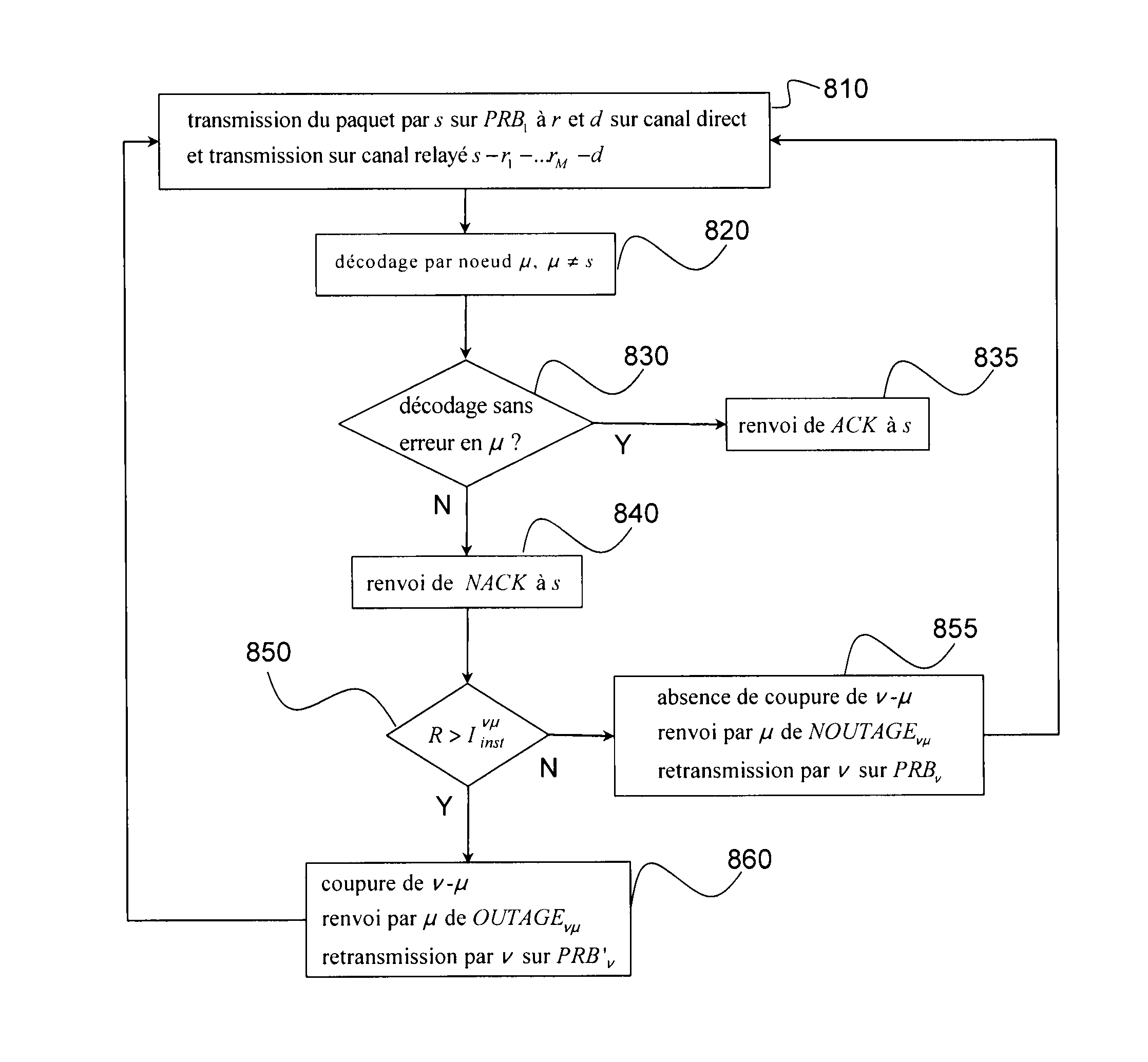
[0130]FIG. 5 illustrates a forwarding method in a cooperative network of the type of FIG. 1A, according to the invention.

[0131]The assumption is here that the cooperative network comprises a source terminal s, a destination terminal d, and a non-empty set of relay terminals, Λr. In general, the cooperative network can be considered as a directed graph the nodes of which are the terminals, the segments of which are the links between terminals, the direction of a segment being given by the direction of transmission.

[0132]The cooperation policy of FIG. 1A is going to be considered, in other words, there is a directed path nsd in the graph, starting at s and leading to d and going through an ordered sequence of relays {r1, r2, . . . , rM} with M≧1. Ω={s, r1, . . . , rM, d} is defined as the ordered sequence of the nodes of the path nsd, and Ωμ={s, r1, . . . , rμ-1} as the ordered sequence of the predecessors of the node μ, with the same relation of order as before. Conventionally, Ω1={s...


PUM


Abstract

The invention relates to a packet forwarding method in a cooperative network implementing a source terminal, a destination terminal, and at least one relay terminal. In case of a packet decoding error in a node of the network, this method, depending on the outage state of a direct or relayed channel between two nodes of the network, enables a determination of the node(s) having to perform retransmission of the packet and if applicable, the transmission resource(s) to be used.

Description

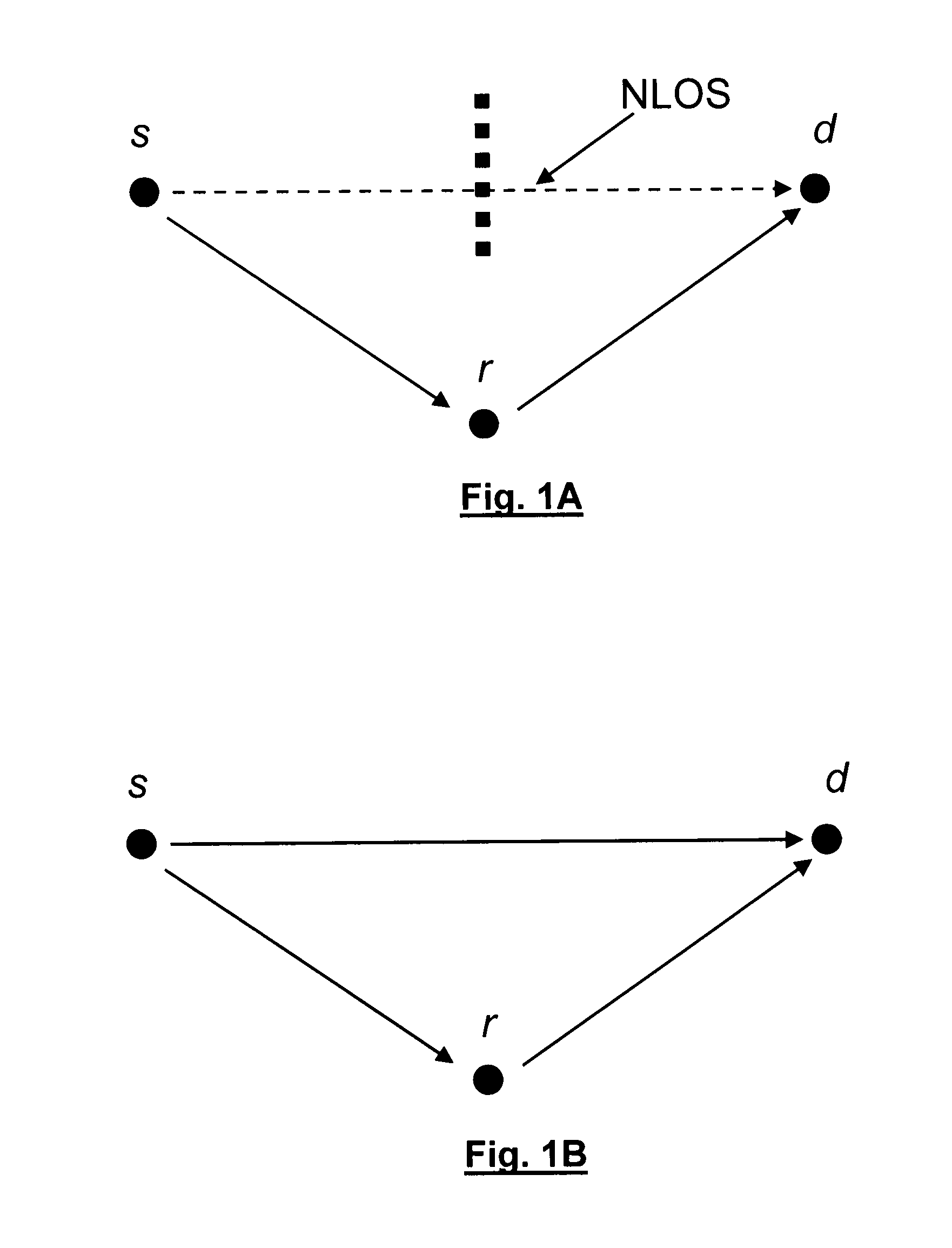
TECHNICAL FIELD[0001]This invention relates in general to cooperative communication systems. In particular, it is applicable to OFDMA-type (Orthogonal Frequency Division Multiple Access) systems, e.g. in WiMAX or 3GPP / LTE systems.BACKGROUND OF THE INVENTION[0002]Cooperative wireless communication systems are known to provide larger coverage and lesser sensitivity to fading than conventional cellular systems. A description of wireless systems of the cooperative type is for instance to be found in the article by J. N. Laneman and G. W. Wornell, entitled “Exploiting distributed spatial diversity in wireless networks”, published October 2000 in Proc. Allerton Conf. on Comm., Contr. and Computing.[0003]FIG. 1A schematically illustrates a first type of cooperation policy in such a system. The source terminal s transmits a data flow to a relay terminal r. The relay terminal receives the data flow and forwards it, possibly after decoding and recoding the same, to the destination terminal s....

Claims


Application Information

Patent Timeline
IPC IPC(8): H04L12/24
CPCH04L1/1825H04L1/1893H04L5/0023H04L5/006H04L27/00H04L2001/0097H04L1/18H04W72/04H04L25/0232H04B7/15557H04B7/15592
Inventor KTENAS, DIMITRICALVANESE STRINATI, EMILIO
Owner COMMISSARIAT A LENERGIE ATOMIQUE ET AUX ENERGIES ALTERNATIVES
Learn More