
Dishwasher

a technology of turbidity measurement and sensor, which is applied in the field of turbidity measurement, can solve the problems of reducing the useful range of light-sensitive elements used in the sensor, affecting the accuracy of the measurement, so as to improve the sensor, improve the accuracy, and improve the effect of sensor quality

Active Publication Date: 2011-11-10
ELECTROLUX HOME PROD CORP NV
View PDF8 Cites 7 Cited by
  • Summary
  • Abstract
  • Description
  • Claims
  • Application Information

AI Technical Summary

Benefits of technology

In view of the above, it would be desirable to achieve an improved sensor and / or method for measuring the turbidity of a fluid. In particular, it would be desirable to achieve a turbidity sensor having a wider operating range than previously available sensors. The sensor should, advantageously, have a simple and / or robust mechanical construction, and, further advantageously, be free of movable parts. Moreover, it would be advantageous to achieve a sensor which is durable and / or energy-lean.
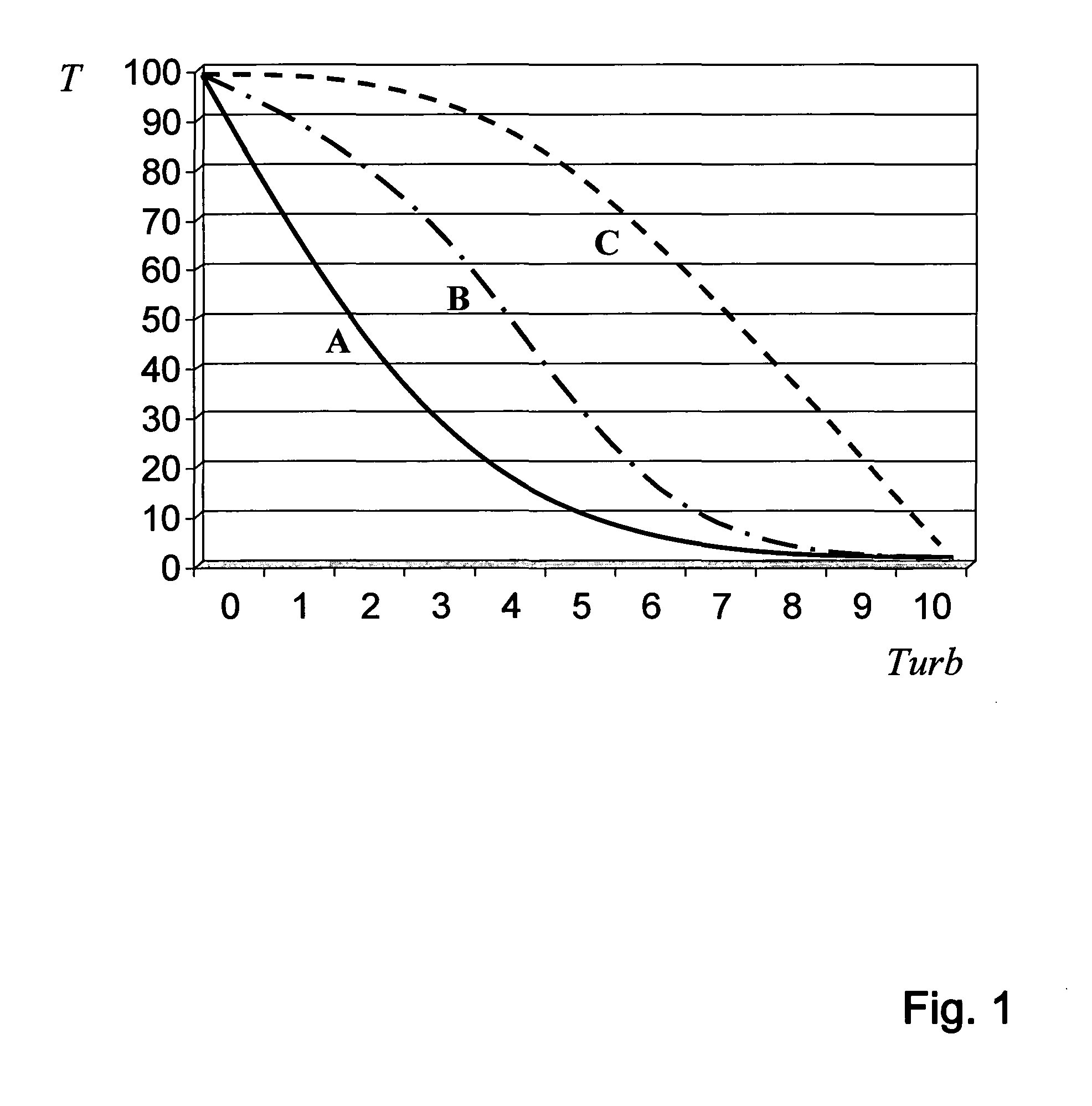
However, the inventors have found that such turbidity sensors can be improved by making the radiant intensity I0 of the light emitted by the light source selectable in dependence of the current turbidity. This can increase the resolving power of the sensor because the sensitivity to an error in the received light intensity I decreases. Indeed, combining equations (1) and (2) and applying the chain rule, one obtains
Thus, increasing the intensity I0 of the light emitted by the light source can make the turbidity measurements more accurate. Yet, to achieve an extension of the operating range of the turbidity sensor, it may be advantageous to control the emitted radiant intensity actively. Use of a high emitted radiant intensity throughout may otherwise cause saturation of the light-sensitive element at low turbidity.
In one embodiment of the invention, the light source of the turbidity sensor is a solid-state lighting device. For instance, the solid-state lighting device may be a LED. LEDs typically have a long lifetime and low power consumption and can, therefore, suitably be used as the light source of the turbidity sensor.
In some embodiments of the invention, there is provided one or more means for favouring emission and / or reception along an optical path between the light source and the light-sensitive element. If preferred directions of the light source and the light-sensitive elements are aligned and perpendicular to the fluid interfaces, then the optical path can be thought of as a straight line. Such means for favouring transmission along the optical axis may include focusing lenses or lens assemblies and / or collimators, and may be provided either on the light-emitting side or the light-receiving side, or both. In one embodiment of the invention, a lens is provided after the light source, where it may focus light emitted by the light source. In one embodiment, a collimator can be provided before the light-sensitive element, where it may prevent light from reaching the light-sensitive element from other directions than a direct optical path from the light source.

Problems solved by technology

While generally a stable relationship exists between transmittance and turbidity for a specific type of particles, the quality of the turbidity measurements may be a limiting factor for the accuracy.
This shortcoming is partly due to the limited useful range of the light-sensitive elements used in the sensors.
Indeed, the correlation between the output of the element and the radiant intensity of received light may degenerate when a saturation level is exceeded.
Conversely, for intensities below the sensitivity threshold of the light-sensitive element, the signal may be drowned in noise and may thus be impossible or at least difficult to detect.
Accordingly, it is understood that available turbidity sensors have some limitations.

Method used


Image

  • Dishwasher
  • Dishwasher
  • Dishwasher

Examples


Embodiment Construction

The present invention will now be described more fully hereinafter with reference to the accompanying drawings, in which certain embodiments of the invention are shown. This invention may, however, be embodied in many different forms and should not be construed as limited to the embodiments set forth herein; rather, these embodiments are provided by way of example so that this disclosure will be thorough and complete, and will fully convey the scope of the invention to those skilled in the art. Furthermore, like numbers refer to like elements throughout.

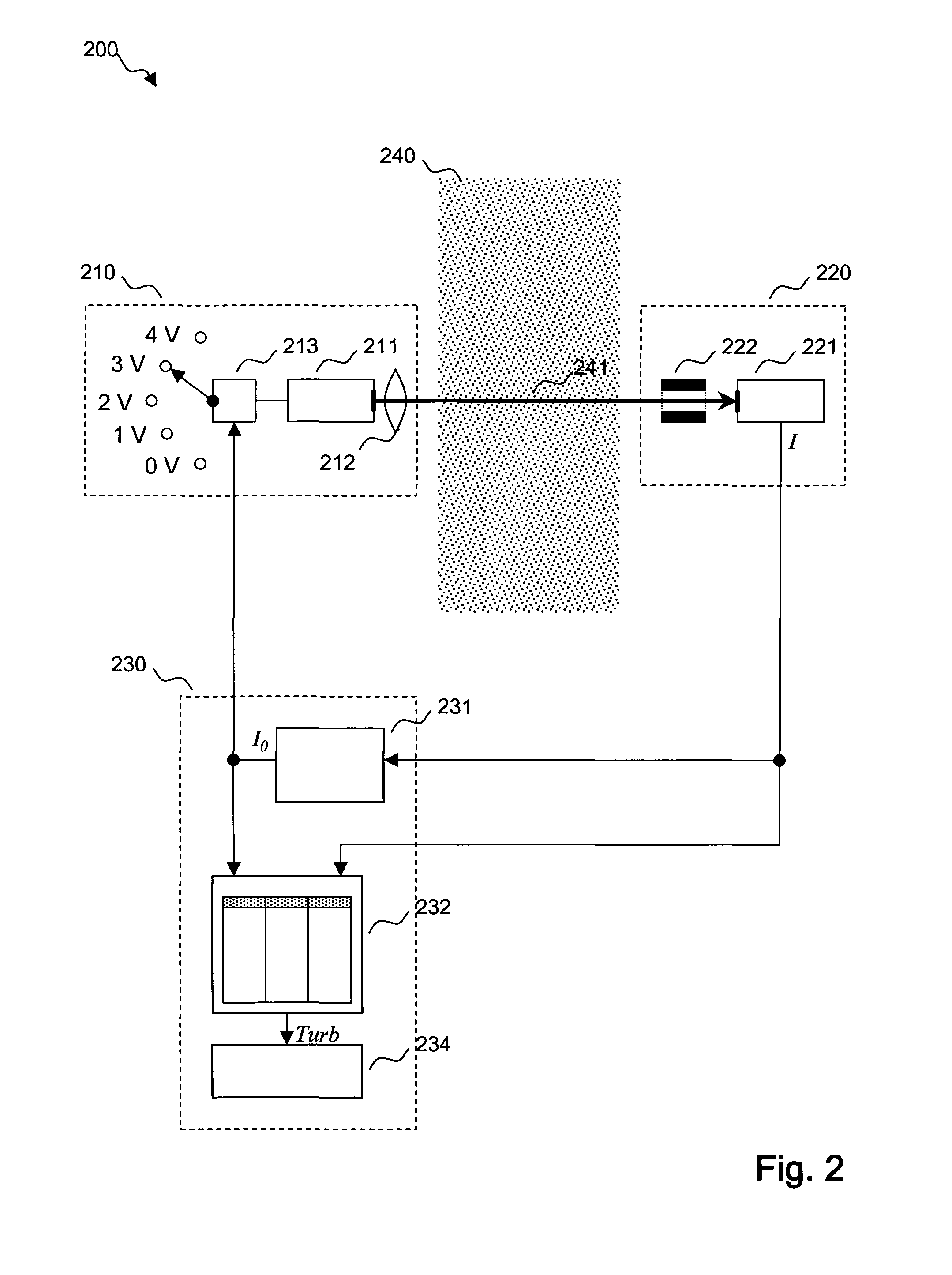
In accordance with an exemplary embodiment of the invention, FIG. 2 shows a sensor 200 for measuring the turbidity of a fluid 240. The sensor 200 according to this exemplary embodiment, which is here represented in block-diagram form, comprises a light-emitting portion 210, a light-receiving portion 220 and a processing and controlling portion 230. The light-emitting 210 and light-receiving 220 portions are so positioned that light e...


PUM

PropertyMeasurementUnit
turbidityaaaaaaaaaa
transmittanceaaaaaaaaaa
wavelength intervalaaaaaaaaaa

Abstract

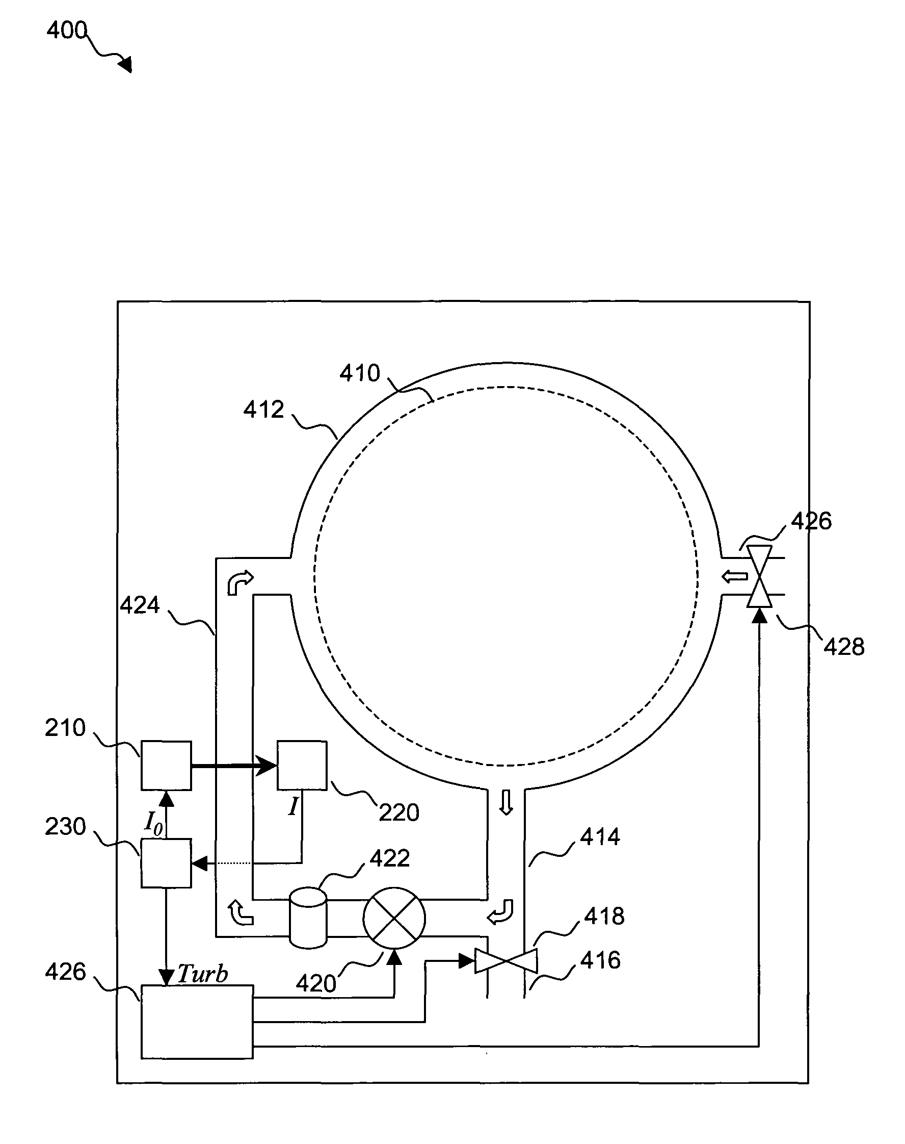
A turbidity sensor for use in a machine for washing articles, e.g., a washing machine (400). The turbidity sensor comprises a light source (210) for emitting light. The emitted light has a radiant intensity which is variable. The sensor further comprises a light-sensitive element (220) for receiving light emitted from the light source (210). The light source (211) and the light-sensitive element (220) are positioned relative to each other so that, when the light source (210) is in operation, light emitted from the light source (210) can propagate through a washing liquid contained in the washing machine (400) on its way to the light sensitive element (220). The light-sensitive element (220) is configured to measure the radiant intensity of light received at the light-sensitive element (221). Furthermore, the sensor comprises a controller (230) which is communicatively coupled to the light source (210) and the light-sensitive element (220). The controller (230) is configured to adjust the radiant intensity of the light emitted by the light source (210) in dependence of the measured radiant intensity of light received at the light-sensitive element (220).

Description

TECHNICAL FIELDThe present invention generally relates to a turbidity sensor and a method of measuring the turbidity of a fluid. More particularly, it relates to a turbidity sensor for use in a machine for washing articles, e.g., a dishwasher or a washing machine.BACKGROUNDToday, appliances or machines for washing dishware or clothes in a liquid medium may be equipped with sensors for measuring the turbidity. It is also possible to have a refrigerator with beverage dispensing system equipped with a sensor for measuring turbidity. As used herein the term turbidity generally refers to the concentration of light-scattering or light-absorbing particles suspended in the liquid medium. If turbidity increases in a fluid then, for a given wavelength, the transmittance generally decreases in dependence of, e.g.:the wavelength,the diameter distribution of the suspended particles,the refractive index of the suspended particles, andthe surface properties of the suspended particles.Settling part...

Claims


Application Information

Patent Timeline
Patent Type & Authority Applications(United States)
IPC IPC(8): G01N21/00
CPCA47L15/4297G01N21/8507G01N21/534D06F39/004D06F34/22D06F2103/20D06F2105/56D06F2105/58G01N15/06
Inventor PIMPUTKAR, GIRISHPERS, PER-ERIK
Owner ELECTROLUX HOME PROD CORP NV
Learn More