Electrochemical element electrode producing method, electrochemical element electrode, and electrochemical element

Inactive Publication Date: 2011-11-03
PANASONIC CORP
View PDF0 Cites 5 Cited by
  • Summary
  • Abstract
  • Description
  • Claims
  • Application Information

AI Technical Summary

Benefits of technology

[0040]In accordance with the electrochemical element electrode producing method of the present invention, the projections that are the splash particles existing on the surface of the active material layer store the lithium to expand in the second step of storing the lithium in the active material layer, and thus, the projections can be easily and surely removed in the third step.
[0041]In accordance with the electrochemical element electrode of the present invention, the projections that are the splash particles formed by the vacuum deposition are removed. Therefore, when stacking the electrode and the separator to produce a battery or capacitor, the possibility of the internal short-circuit by the penetration of the separator by the projections can be avoided.
[0042]In accordance with the electrochemical element of the present invention, the projections that are the splash particles formed by the vacuum deposition are removed from the negative electrode. Therefore, the possibility of the internal short-circuit by the penetration of the separator by the projections can be avoided.

Problems solved by technology

It is thought that the bumping of the deposition materials occurs due to impurities contained in the deposition materials in the crucible or temperature irregularity in the crucible.
It is possible to reduce the bumping, but it is difficult to eliminate the bumping.
Especially when the film formation is carried out for a long period of time while supplying deposition materials, it is difficult to eliminate the bumping.

Method used


Image

  • Electrochemical element electrode producing method, electrochemical element electrode, and electrochemical element
  • Electrochemical element electrode producing method, electrochemical element electrode, and electrochemical element
  • Electrochemical element electrode producing method, electrochemical element electrode, and electrochemical element

Examples


example

[0102]Hereinafter, the present invention will be explained in more details by using Example. However, the present invention is not limited to Example below.

[0103]First, for the purpose of forming a negative electrode polar plate of a nonaqueous electrolyte secondary battery, the first step was carried out to form a Si thin film on a negative-electrode current collector.

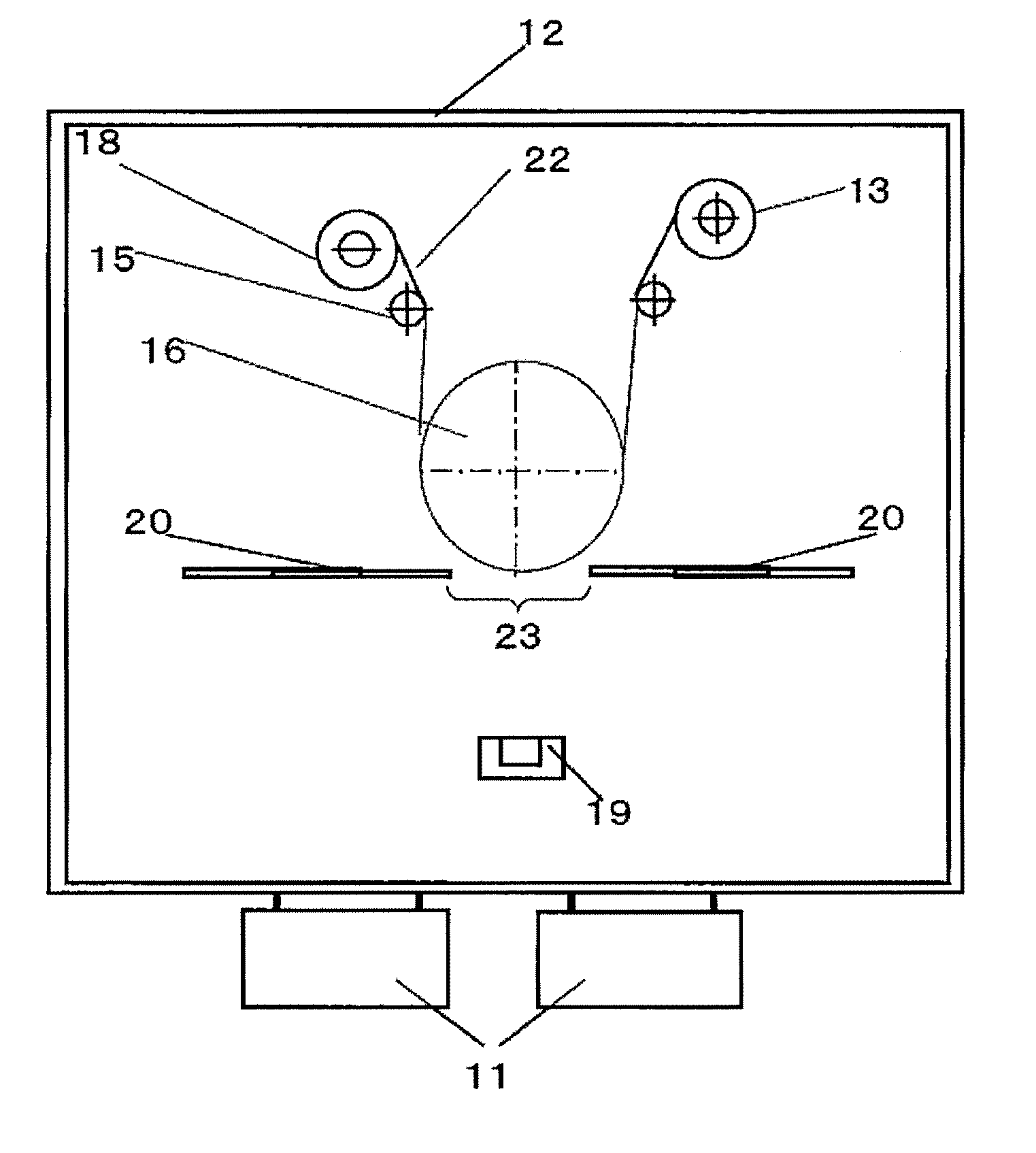
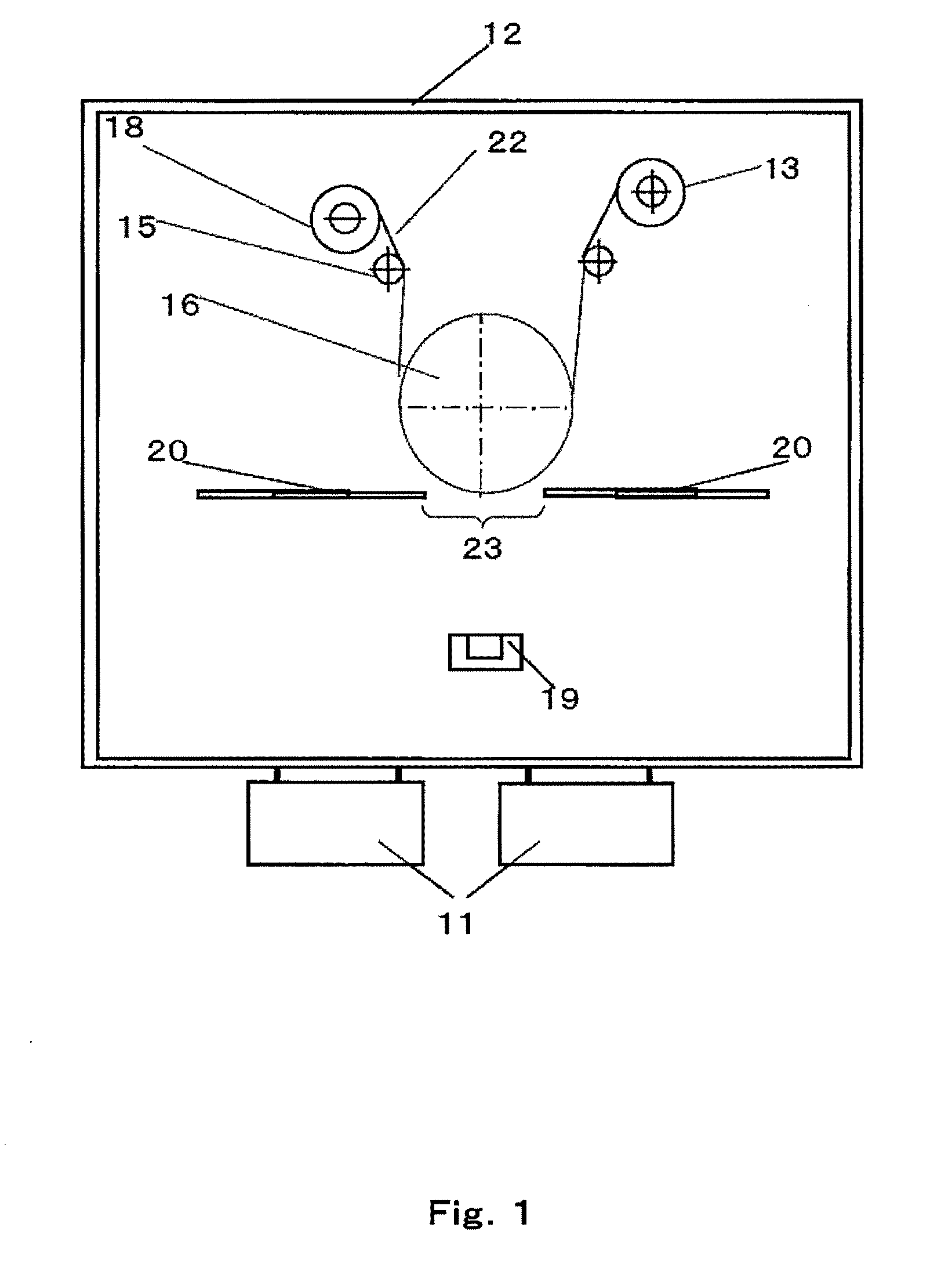
[0104]To be specific, in the configuration of the device shown in FIG. 1, a roughened copper foil (EXP-DT-NC, 35 μm, produced by Furukawa Circuit Foil Co., Ltd.) having a width of 28 cm was used as the substrate, and the position of the shielding plate was adjusted such that the length of the thin film forming portion (23) was set to about 45 cm. The thin film formation source (19) that was a graphite crucible in which highly-pure Si (99.9% pure) was put was placed such that a shortest distance between the thin film formation source (19) and the thin film forming portion (23) was set to 40 cm. The thin film formation ...


PUM

PropertyMeasurementUnit
Fractionaaaaaaaaaa
Fractionaaaaaaaaaa
Diameteraaaaaaaaaa

Abstract

Provided is a method for easily and surely removing projections formed on the surface of an active material layer by a vacuum process when producing an electrochemical element electrode. Carried out to produce the electrochemical element electrode are: a first step of forming an active material layer on a current collector by a vacuum process, the active material layer being capable of storing and emitting lithium; a second step of storing the lithium in the active material layer; and a third step of removing projections on the surface of the active material layer storing the lithium.

Description

TECHNICAL FIELD[0001]The present invention relates to a method for producing an electrochemical element electrode usable in lithium secondary batteries and electrochemical capacitors, an electrochemical element electrode, and an electrochemical element.BACKGROUND ART[0002]In recent years, mobile devices have been reduced in size and increased in functionality, and accordingly, it has been desired to increase the capacities of batteries as power supplies of such mobile devices. A theoretical capacity of carbon currently mainly used as a negative-electrode active material is 372 mAh / g. As an active material which is higher in capacity than carbon, silicon having the theoretical capacity of 4,200 mAh / g is regarded as promising. Therefore, a large number of electrode materials each containing silicon as a major component and a large number of structures of the electrode materials each containing silicon as a major component have been studied.[0003]One of them is an active material layer...

Claims


Application Information

Patent Timeline
IPC IPC(8): H01M4/134B32B3/00H01G4/06C23C28/00B32B38/10H01M4/1395B05D5/12C23C14/24C23C14/58H01G9/00H01G11/06H01G11/22H01G11/24H01G11/30H01G11/86H01M4/13H01M4/139H01M10/058
CPCH01G11/28H01G11/50H01G11/70H01G11/86H01M4/0421Y10T428/24355H01M4/1395H01M4/485Y02E60/122Y02E60/13H01M4/134Y02E60/10Y02P70/50
Inventor KAMIYAMA, YUMAHONDA, KAZUYOSHISHINOKAWA, YASUHARUYANAGI, TOMOFUMI
Owner PANASONIC CORP
Why Eureka
Try Eureka