
Internal structure for aircraft in composite material

a composite material and aircraft technology, applied in the direction of fuselage, sustainable transportation, transportation and packaging, etc., can solve the problem of limiting the weight optimization of the structur

Inactive Publication Date: 2011-11-03
AIRBUS OPERATIONS SL
View PDF3 Cites 12 Cited by
  • Summary
  • Abstract
  • Description
  • Claims
  • Application Information

AI Technical Summary

Benefits of technology

[0010]This invention refers to an internal structure for an aircraft made in composite material, in particular in fuselages for aeronautical structures, which comprises a composite material skin, some stringers integrated by co-bonding or co-curing to the inside of the aforementioned skin and some frames which are either riveted or integrated by co-bonding or co-curing to the inside of the aforementioned skin. The skin in turn comprises zones of increased thickness in the form of strips or integrated lay-up track, in which the thickness of the skin is greater than its thickness in the rest of the section. The stringers are integrated onto these zones of greater thickness by means of a co-bonding or co-curing process. This achieves the isolation of the interface line of the joint between the stringer and the skin from the zone of the skin in which the buckling takes place.
[0011]The above internal structure for the aircraft achieves a design in which the post-buckling capacity is increased, so permitting buckling in the zone of the skin located between stringers which is greater than that permitted by means of a skin which does not comprise zones of greater thickness, without leading to detachment of the stringers from the skin onto which they are arranged, thanks to the interface line of the joint of these stringers being separated or isolated from the zone of the skin which undergoes buckling.
[0014]The main advantages achieved by this invention are as follows: the design of the internal structure is more highly integrated, with greater weight optimization, and provides a structure which is more tolerant to damage, at the same time that the structure saves costs by combining large sheets of base skin to obtain the structure's final configuration.

Problems solved by technology

This limits the weight optimization of the structure.

Method used


Image

  • Internal structure for aircraft in composite material
  • Internal structure for aircraft in composite material
  • Internal structure for aircraft in composite material

Examples


Embodiment Construction

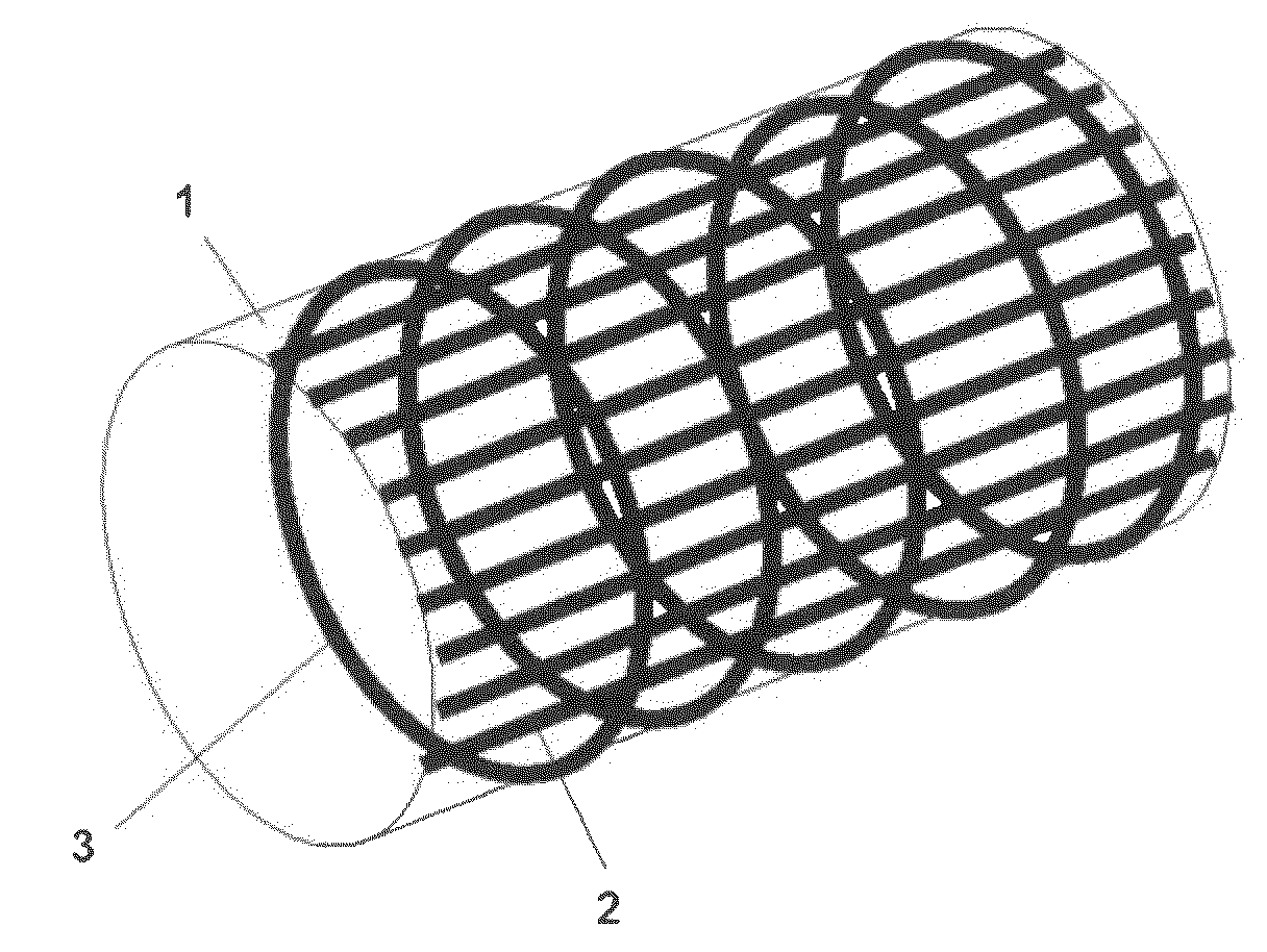
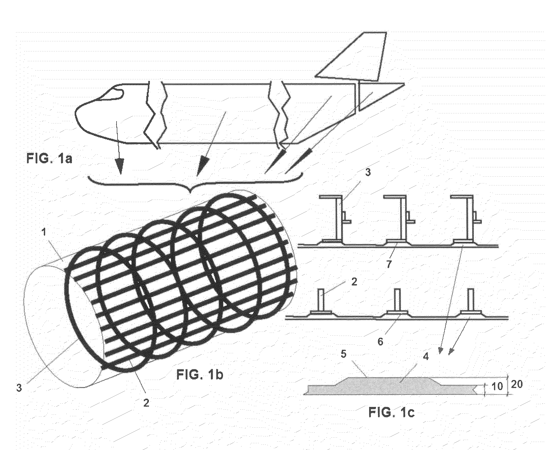
[0022]This invention refers to the internal structure of the fuselage of an aircraft made from composite material. This structure comprises a skin 1 of composite material, some stringers 2 integrated by means of co-bonding or co-curing into the skin 1 and some frames 3. The frames 3 can be riveted or integrated by means of co-bonding or co-curing to the skin 1 of the structure. The skin 1 comprises some zones 4 in which the thickness 20 of the skin 1 is greater than the thickness 10 which this skin 1 has in the rest of its section (see FIGS. 1c and 2c). According to a preferred embodiment, the stringers 2 are integrated into the skin 1 in these zones 4 by means of a co-bonding or co-curing process. With this arrangement the interface line 5 of the joint between the stringers 2 and the skin 1 is as far as possible from the zone of the skin 1 with lower thickness 10, which is the zone of this skin 1 which undergoes buckling.

[0023]The above structure permits the buckling of the skin 1 ...


PUM

PropertyMeasurementUnit
thicknessaaaaaaaaaa
structureaaaaaaaaaa
weightaaaaaaaaaa

Abstract

Internal structure for aircraft comprising a skin (1) of composite material, some stringers (2) of composite material integrated into the interior of the aforementioned skin (1) and some frames (3) of composite material, comprising the skin (1) with some zones (4) in which its thickness (20) is greater than the thickness (10) this skin (1) has in the rest of its section, with the stringers (2) integrated into these zones (4) of the skin (1), achieving with this arrangement the isolation of the interface line (5) of the stringer (2) joint with the skin (1) from the skin (1) with thickness (10).

Description

FIELD OF THE INVENTION[0001]This invention refers to an internal structure for an aircraft made from composite material, in particular for fuselages for aeronautical structures.BACKGROUND OF THE INVENTION[0002]It is widely known that aeronautical structures are designed seeking to optimize them to minimize weight while meeting the criteria for strength and stiffness. One consequence of this requirement is the ever more extensive use of composite materials in primary structures as, by appropriately applying the aforementioned composite materials, significant savings in weight can be made in comparison to a design with a metallic material and a series of other advantages obtained.[0003]It is known as an integrated structure when the different elements of which it is made up are manufactured at the same time in a single process: this is the other advantage of the use of composite materials. This feature leads to cost savings for structures made from composite materials as it greatly re...

Claims


Application Information

Patent Timeline
Patent Type & Authority Applications(United States)
IPC IPC(8): B64C1/06B32B3/00
CPCB64C1/068B64C1/12Y10T428/24612Y02T50/433B64C2001/0072Y02T50/40
Inventor CRUZ DOMINGUEZ, FRANCISCO JOSEAREVALO RODRIGUEZ, ELENA
Owner AIRBUS OPERATIONS SL
Learn More