
Cord Tension Control for Top Down/Bottom Up Covering for Architectural Openings

a technology of top down/bottom up covering and tension control, which is applied in the direction of door/window protective devices, constructions, building components, etc., can solve problems such as malfunction of coverings, and achieve the effect of avoiding entanglement of lift cords

Active Publication Date: 2011-11-03
HUNTER DOUGLAS INC
View PDF8 Cites 15 Cited by
  • Summary
  • Abstract
  • Description
  • Claims
  • Application Information

AI Technical Summary

Benefits of technology

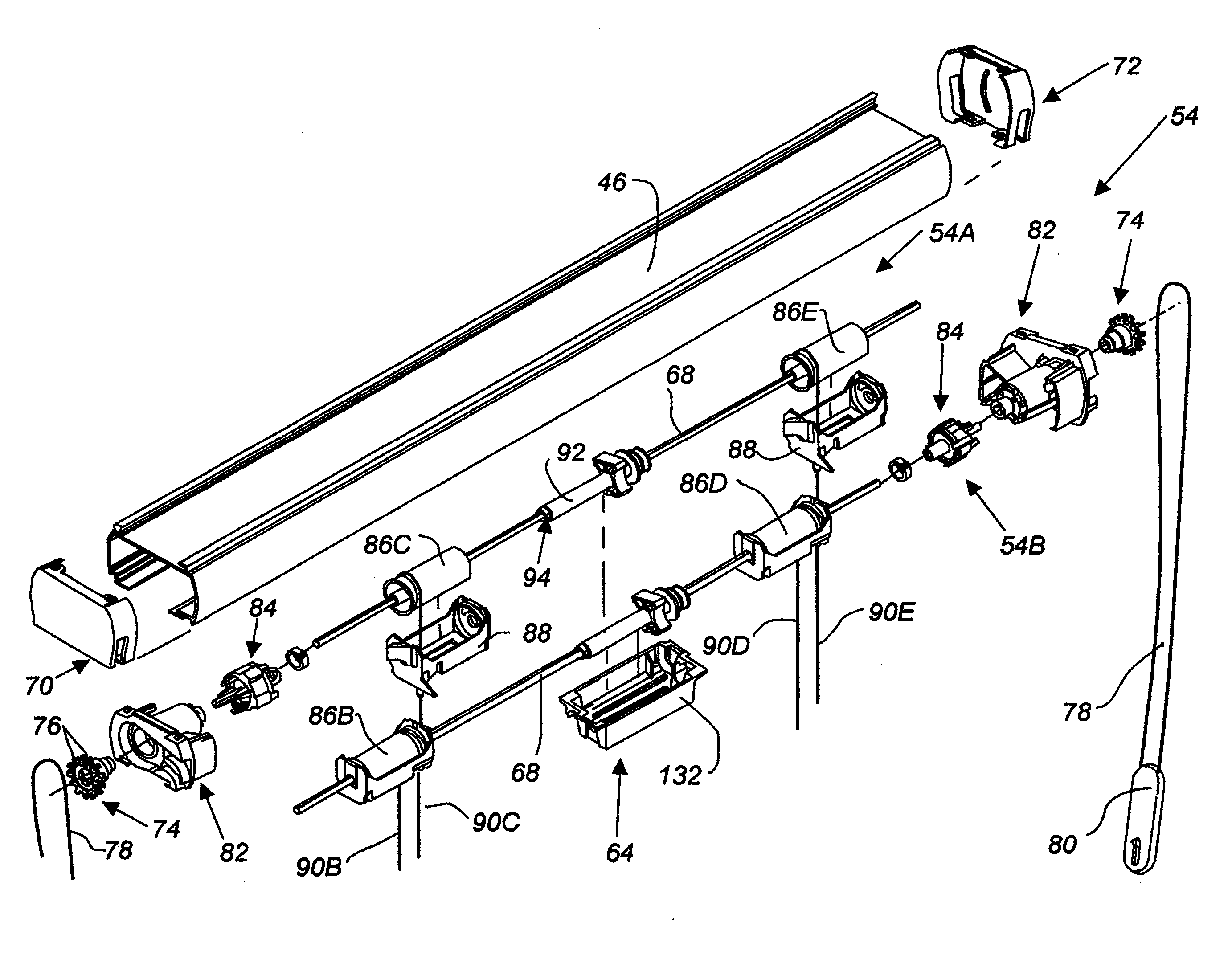
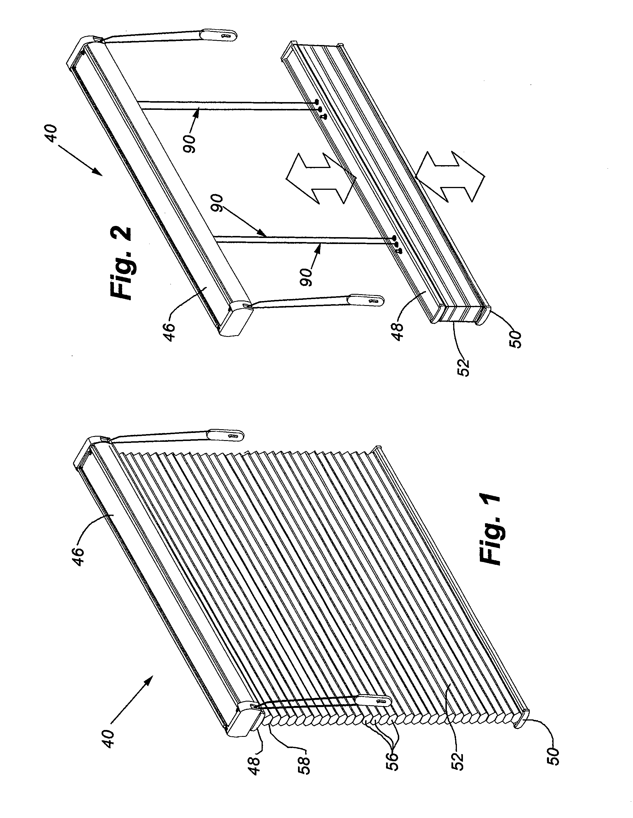
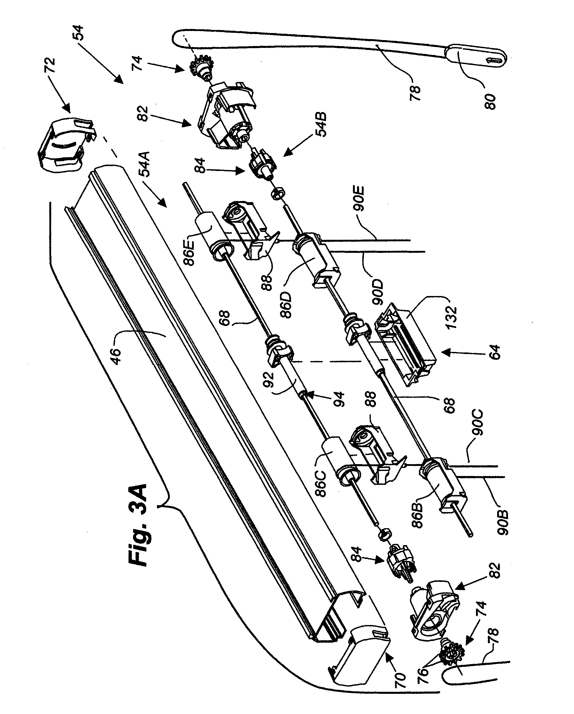
[0009]A cord tension control system pursuant to the present invention has been designed to avoid entanglement of lift cords about their wrap spools within a headrail of a retractable covering of the top down / bottom up type. The invention addresses the problem by providing pairs of adjacent threaded rods adapted to rotate in unison with wrap spools with which they are associated and with the wrap spools further being associated with a particular rail to which collapsible shade material is attached. As a rail is raised or lowered with an associated lift cord, thus effecting rotation of a cord spool and the wrapping of a lift cord thereabout, a threaded shaft rotates in unison therewith and includes an abutment nut which translates along the length of the threaded shaft as it rotates. Pairs of the threaded shafts, with one shaft of each pair being associated with each rail, are closely enough positioned so that the abutment nuts on each shaft will engage each other at preselected positions of the nuts so that movement of one rail past another can be avoided at any desired relative location of the rails thus avoiding entanglement of the lift cords associated with each wrap spool.

Problems solved by technology

The problem encountered with such retractable coverings resides in the fact that the lift cords themselves are typically wrapped around spools within the headrail and when one movable rail is moved past a position occupied by another movable rail, the lift cords sometimes become entangled on their associated spools causing malfunctioning of the covering.

Method used


Image

  • Cord Tension Control for Top Down/Bottom Up Covering for Architectural Openings
  • Cord Tension Control for Top Down/Bottom Up Covering for Architectural Openings
  • Cord Tension Control for Top Down/Bottom Up Covering for Architectural Openings

Examples


second embodiment

[0083]Looking at FIGS. 17A-18, this arrangement 150 of the top down / bottom up covering can be seen to include a headrail 46 identical to that described in connection with the first arrangement, a top panel 156 of collapsible shade material, and a bottom panel 158 of collapsible shade material. The top panel 156 of shade material has its uppermost cell suspended from the headrail 46 in a conventional manner, such as with an anchor strip (not shown), and its bottom edge connected to a top rail 160 through use of an anchor strip through the lowermost cell of the top panel. The uppermost cell of the bottom panel 158 is connected to the lower surface of a middle rail 162, again with an anchor strip (not shown) or through any other suitable system, with the bottom or lowermost cell of the bottom panel being connected to a bottom rail 164 in a similar manner. The bottom rail of this arrangement of the covering is secured to the threshold 166 (FIGS. 21A-21E) of the framework of the architec...

first embodiment

[0088]The cord tension control system 152, as mentioned, further includes an abutment nut 120 on each threaded shaft with the abutment nuts, as mentioned previously, being identical to those described in connection with the cord tension control system. The threaded shafts are rotatably supported within an open topped housing 200 shown best in FIG. 27 and shown in FIGS. 24-26 in operative relationship with threaded shafts 174A and 174B. As seen in FIG. 22, however, it will be appreciated the threaded shafts are offset longitudinally of each other similar to the first described embodiment and have the opposite ends of the threaded shafts rotatably received in cradles 202 that positively position the threaded shafts relative to the housing. The housing, of course, is fixedly positioned within the headrail 46 in any suitable manner.

[0089]Referring first to the upper threaded shaft 174A, as viewed in FIG. 22 as well as referencing FIGS. 24-27, it will be appreciated the housing 200 has a...


PUM


Abstract

Cord tensioning systems are provided for top down / bottom up coverings to prevent entanglement of lift cords about associated wrap spools by correlating rotation of the wrap spools with translating threaded nuts mounted on threaded shafts rotating in unison with the wrap spools whereby abutment of nuts associated with lift spools prevent over movement of rails associated with the spools and thus entanglement of the lift cords associated therewith.

Description

BACKGROUND OF THE INVENTION[0001]1. Field of the Invention[0002]The present invention relates generally to top down / bottom up coverings for architectural openings and more particularly to a system for preventing entanglement of lift cords used in such coverings for raising and lowering horizontal rails in the covering between extended and retracted positions.[0003]2. Description of the Relevant Art[0004]Retractable coverings for architectural openings have been in use for many years. Early forms of such retractable coverings were referred to as Venetian blinds wherein a plurality of horizontally disposed, vertically spaceable slats are supported on cord ladders and utilize a control system that allows the slats to be raised or lowered to move the covering between retracted and extended positions relative to the architectural opening in which the covering is mounted. The slats can also be tilted about horizontal longitudinal axes to move the covering between open and closed positions...

Claims


Application Information

Patent Timeline
IPC IPC(8): A47H5/032
CPCE06B9/262E06B2009/6881E06B2009/2627E06B2009/2441E06B9/322
Inventor DREW, TERRENCE M.FEARNOW, JON C.SPRAY, JEFFREY L.
Owner HUNTER DOUGLAS INC
Learn More