
Maintenance and management system for endotracheal tube in intubation

Inactive Publication Date: 2011-11-03
NAT UNIV CORP KYUSHU INST OF TECH (JP)
View PDF6 Cites 14 Cited by
  • Summary
  • Abstract
  • Description
  • Claims
  • Application Information

AI Technical Summary

Benefits of technology

[0025]A maintenance and management system for a tracheal tube constructed according to the present invention excels in permitting diagnosis of not only the complications which could be measured with even conventional systems, but also the modest airway obstruction which was hard to be found by the traditional systems. The system of the present invention, moreover, is excellent in permitting providing the optimal cuff-pressure estimate customized for every patient rather than providing only the automatic regulation of the cuff pressure, which has been carried out with conventional systems.
[0026]The system constructed according to the present invention has different advantageous effects, for example, checking whether the endotracheal tube after having passed through the glottis is placed properly in the trachea, not in the esophagus, confirming no occurrence of the stenosis in the endotracheal tube caused by sputum clogging, checking whether the endotracheal tube is falling away from the airway, confirming there is no air leak through the airway, permitting storage and monitoring of measured data, automatic diagnosis of the associated complications, and further taking information about reproducing function of sound in the breathing circuit, and so on.

Problems solved by technology

Nevertheless, many people would suffer fatal risks of postoperative complications if discovered too late.
With the prior cuff-pressure regulator, too much of the air can be released out of the cuff whenever the cuff pressure rose not only at the time of air pouring phase but also even under medical care.

Method used


Image

  • Maintenance and management system for endotracheal tube in intubation
  • Maintenance and management system for endotracheal tube in intubation
  • Maintenance and management system for endotracheal tube in intubation

Examples


Embodiment Construction

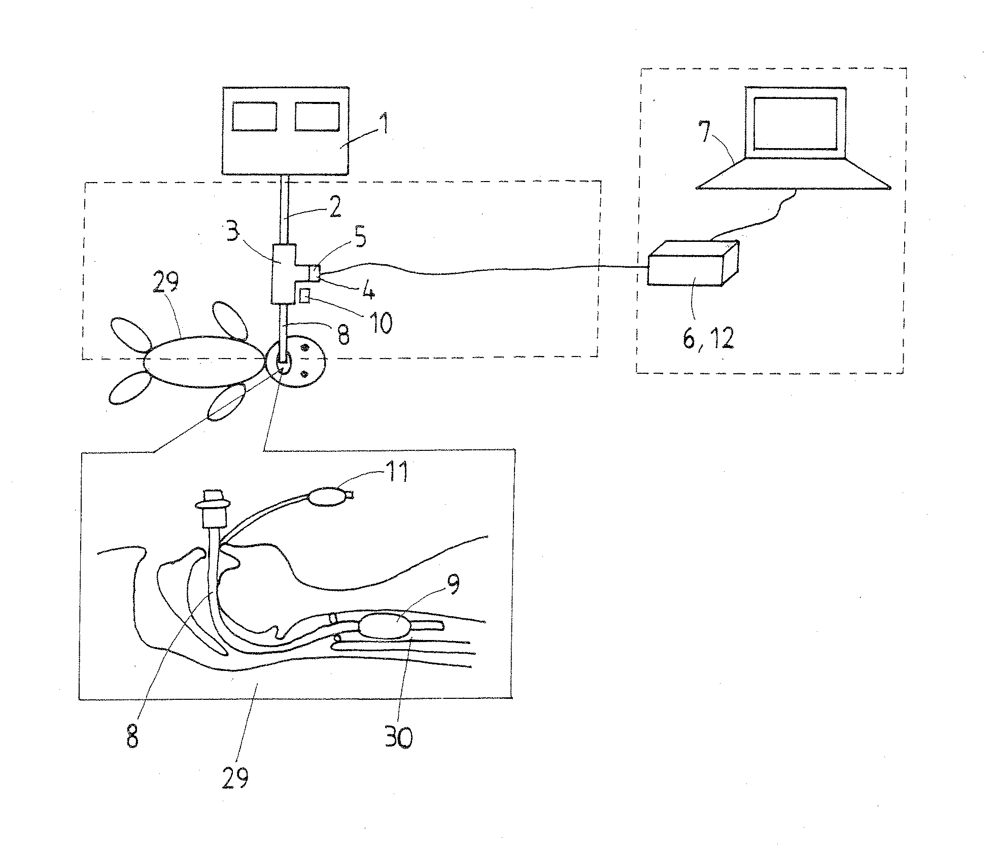
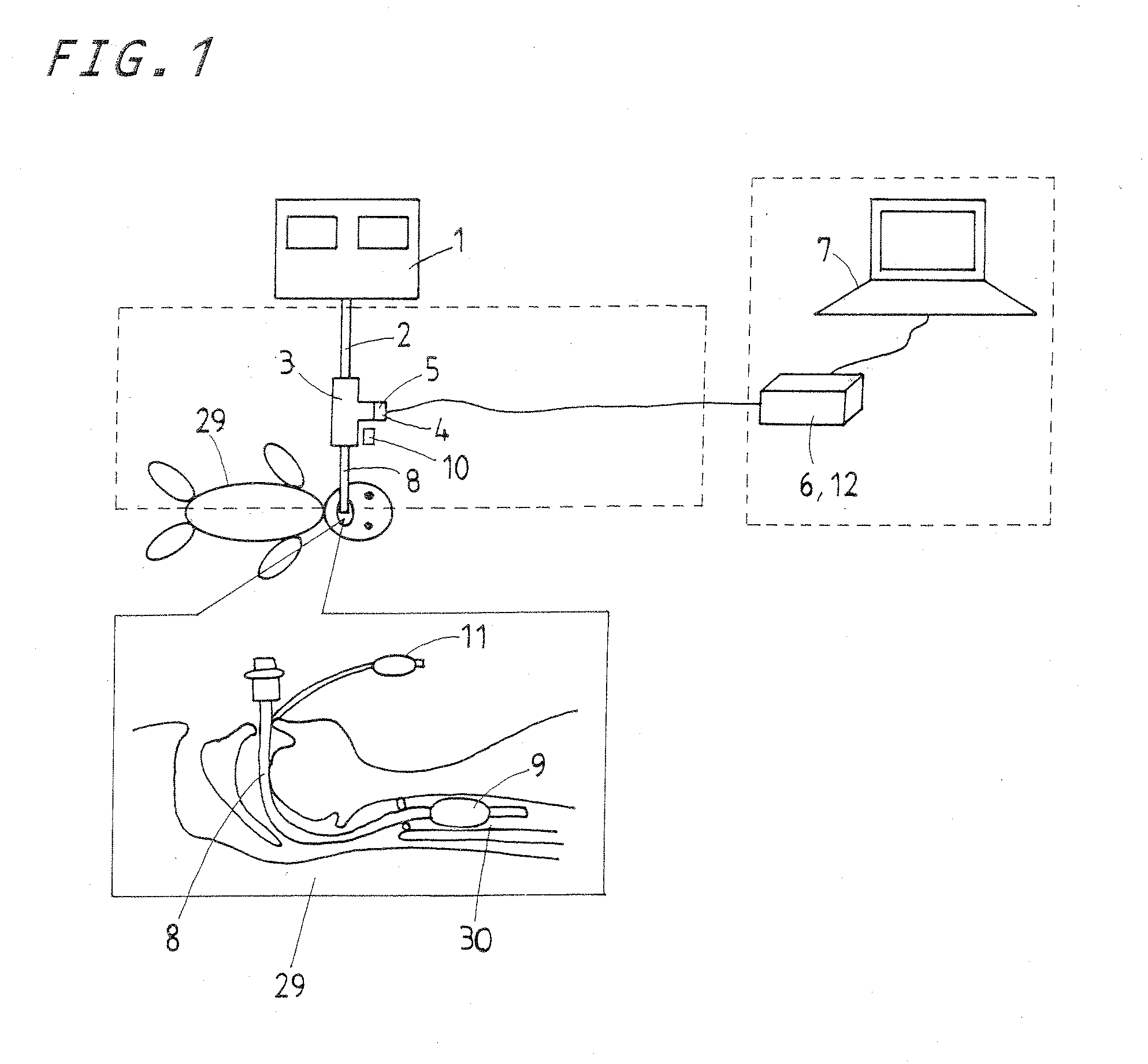
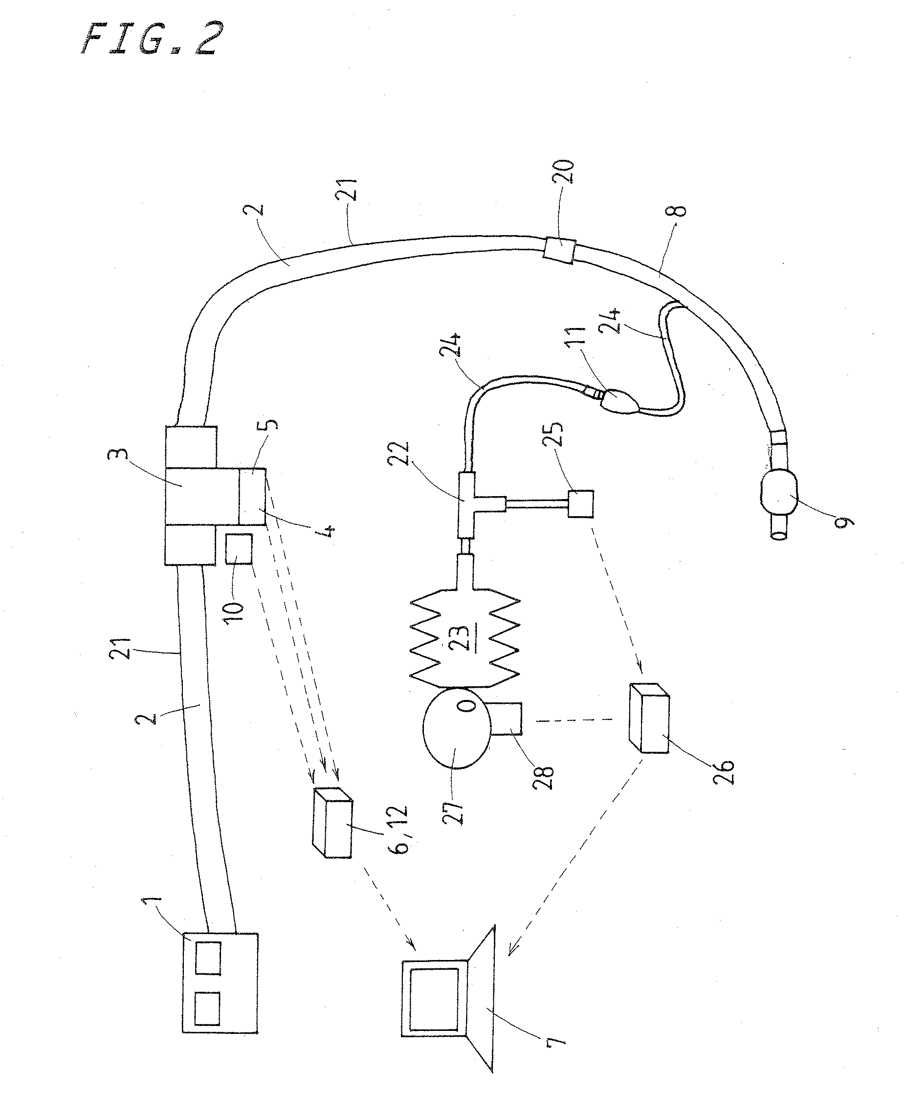
[0067]A preferred embodiment of a maintenance and management system for an endotracheal tube according to the present invention will be described hereinafter in connection with the accompanying drawings. The maintenance and management system for the endotracheal tube as shown in FIGS. 1 and 2 has a ventilator circuit 2 of a tube connected with a mechanical ventilator 1, a microphone 4 and a pressure sensor 5, or a first pressure sensor, mounted on the ventilator circuit 2 through a T-shaped connector 3, and another microphone 10 installed nearby the connector 3. An endotracheal tube 8 to be inserted into a trachea or airway 30 of a patient 29 is communicated with the connector 3. Thus, the endotracheal tube 8 may be easily connected to the ventilator 1 through the connector 3 with accompanying both the microphone 4 and the pressure sensor 5. Two sensors, namely the microphone 4 and the pressure sensor 5, issue signals, respectively, which are sent through a signal processing circuit...


PUM


Abstract

A maintenance and management system for tracheal tube in tracheal intubation makes it easier or steadier to identify endotracheal tube placement in the airway, check a tracheal stenosis due to sputum clogging, confirm a breakaway of the tube out of the airway, store and monitor measured data, diagnose automatically the complications, and obtain data for reproducing function of sound in a breath circuit. A ventilator tube is connected to the endotracheal tube and provided therein with a microphone to sense a breath sound transmitted via the endotracheal tube and a pressure sensing element to measure a circuit pressure in the ventilator circuit for the endotracheal tube. The data derived from the sensing elements is processed in a personal computer to be used to measure whether the breath sound and the circuit pressure are within a range of a prescribed value.

Description

FIELD OF THE INVENTION[0001]The present invention relates generally to a tracheal intubation and more particularly to a system to maintain or keep in place and manage or administer adequately an endotracheal tube after a trachea or an airway has been intubated for mechanical ventilation at, for example, medical practice sites of anesthesia, intensive care, first-aid care and so on.BACKGROUND AND REVIEW OF RELATED TECHNOLOGY[0002]The tracheal intubation is generally a standard medical care in which an endotracheal tube is inserted or introduced for mechanical ventilation into a trachea of a patient who has no airway management and then no sufficient ventilation and no oxygenation of blood at medical practice sites of anesthesia, intensive care, first-aid care and so on. With the tracheal intubation as stated earlier, the trachea is usually intubated with the endotracheal tube while a laryngoscope makes a view of the vocal folds and the glottis possible. The endotracheal tube in the t...

Claims


Application Information

Patent Timeline
IPC IPC(8): A61M16/04
CPCA61M16/0051A61M16/04A61M16/044A61M2016/0027A61M16/0411A61M2205/18A61M2205/3375A61M2205/7518A61M16/0833A61M2205/07A61M16/0841A61M16/026
Inventor TAGAWA, YOSHIHIKOMIMURA, KOJIINADA, TOMOHISAMATSUMOTO, TAKAHIRO
Owner NAT UNIV CORP KYUSHU INST OF TECH (JP)
Learn More